Simple Polaroid-based Polarizing Apparatus

The Polaroid

One is going to need a quantity of polarizing film (polaroid) for any easily constructed polarizing apparatus. Fortunately, the material is inexpensive and readily available from any number of sources online. When seeking the material for construction one should purchase linear polarizing polaroid rather than the circularly polarizing filters common in photography. Do not hope to luck out with a bargain by purchasing the sort of polarizing film sold for use with LCD screen repair and refurbishment, it will not prove suitable.

The size of the film purchased will vary depending on the sort of apparatus which is planned but in most cases a small piece of five square centimeters (two square inches) is enough. One shouldn’t feel obligated to purchase expensive polaroid whether that expense is attributed to the supposed quality of the film (the perfectness of the polarization) or its thickness or any protective coating. Very often one may have the option to purchase polaroid in varying thickness, and the thicker film is useful for applications that require a large self-supporting filter, but in many cases the thinner product is preferable simply because it is easier to work with.

The Example

Not one to miss out on a potential market, Bausch & Lomb marketed a simple polarizing apparatus for users who did not require (or have the budget for) the more complex prism-based variety. Below is seen an exceedingly simple set composed of polarizing film set into light metal frames. One portion is a 21mm disc and the other is of 32mm, a split ring retainer is included. The concise instructions on the reverse of the box direct the user to install the smaller disc in a standard eyepiece by separating the components of the eyepiece so that the disc may rest upon the eyepiece diaphragm. The eyepiece itself then becomes the analyzer which is in this instance the rotating component. The 32mm disc is sized to be compatible with filters used in most substages and serves as the polarizer.

Simple commercial example of a type anyone can produce.

Simple commercial example of a type anyone can produce.

Right away one can see that an essentially identical set may be produced for just a few dollars. If one is loath to risk the cleanliness of an ocular by separating the components to insert the analyzer, a cap may be fashioned that holds the polaroid and fits above the microscopes eyepiece. It will work in precisely the same fashion and has the advantage of not requiring an ocular be put aside for polarizing work only. Regrettably, one will recognize very quickly that such a set, whether the analyzer is integrated with an ocular or placed over it, will not work effectively on a binocular or trinocular microscope.

Special Considerations

For microscopes equipped with binocular or trinocular heads, one should place the analyzer in a location such that it acts upon the light prior to that light being sent into the eyepiece or photo tubes. Fortunately it is often a simple matter to remove the microscopes head and place the analyzer within. Once the analyzer is positioned one must look to the way in which the polarizer may be accommodated. In most cases it is not advisable to use a 32mm disc placed in the substage filter holder simply because rotating it once positioned is inconvenient. Very often only a small effort need be expended to create a holder that may be placed in the substage to facilitate rotating the polarizer. In any case one should endeavor to arrange polarizer and analyzer so that both may be quickly removed or installed, and one of the two is rotatable.

Improvised polarizer and analyzer in place on AO Spencer microscope

Improvised polarizer and analyzer in place on AO Spencer microscope

In the photograph at right one can see that a simple disk of polarizing film has been placed intermediate to the objective turret and trinocular head of this AO Spencer Microstar microscope to serve as the analyzer. A rotating polarizer has been constructed from a plastic film canister lid and aluminum screw cap, it fits conveniently in the 32mm filter recess of the microscopes integrated illuminator. By virtue of the microscopes construction only one finger screw needs to be loosened to remove the head and place the analyzer. For ease of handling, and so that it may serve double duty the analyzer was cut to a size of 32mm and may be used as the polarizer when placed in the substage filter holder of a monocular microscope. One should note that the polarizer is of a size that no light may pass out of the integrated illuminator that does not pass through the polarizer.

Next time: eye-candy! A few nice photomicrographs of slides with bright-filed and polarized light. -K

Polarized Light Microscopy

The Background

Very often those introduced to light microscopy, and enthusiastic about it, rapidly become dissatisfied with not being able to work with all of the methods read about in books. From differential interference to phase contrast there are more than a few methods of light microscopy that one may long for, but lack the budget to pursue. Fortunately, one exotic sort of light microscopy has been doing nothing but becoming more accessible for the last one hundred years or so; that method of course is polarized light microscopy. A step beyond simple things like throwing the mirror to one side for oblique lighting, or slipping a patch stop into the filter holder for dark field or even Rheinberg illumination, polarized light microscopy is now more economical than ever.

When light microscopy was just finding its stride among professionals and hobbyists, opticians sold microscopy equipment in much the same was as furniture stores pursue their trade today. One might purchase a central item and then outfit it with a number of accompaniments either immediately or a bit down the line. In many ways this meant that one could pursue the limits of microscopy as an amateur as easily as any professional. Regrettably, it also meant that the cutting edge in microscopy as pursued by professionals was just beyond the financial means of most amateurs. Apparatus for polarized light microscopy was no exception.

With the patent of polaroid (the product as opposed to the company) in 1929 it became possible to produce polarized light microscopy apparatus for far less than had been possible previously. From then, the quality of polarizing films has increased while the cost of manufacture has decreased.  At this very moment one is likely within reach of a number of polarizing filters. Liquid crystal displays, windows, eyeglasses, and sunglasses are all common made with polarizing filters. It’s only a slight stretch to say that polarizing filters are everywhere, and the ability of the internet to connect suppliers with clients has made finding the product simple and fast.

The What & Why of Polarization

As with most specialized methods of illumination, polarized light microscopy has nothing more as its goal than increasing the microscopists understanding of their specimen. With polarized light microscopy visibility of some structures is outright increased and specimens or particular structures glow brilliantly in the dark field of crossed polarizers. Crystals may turn from bland colorless structures into colorful landscapes that provide a key to upstanding their form and composition.

The increased visibility offered by polarized light microscopy is the product of two polarizing filters. One filter, called the polarizer, is placed below the specimen so that the light which passes through it (and illuminates the specimen) is polarized. A second polarizing filter, called the analyzer, is then placed above the specimen so that the light which reaches the eye of the observer has passed through two polarizing filters. A polarizer or analyzer used on its own will not reveal much but with both one can determine the following with a little effort:

  • Whether the object is polarizing (ainsotropic) or isotropic (non-polarizing)
  • Whether it is uniaxial or biaxial
  • Whether it is subject to interference phenomena
  • Whether it rotates the plane of polarization
  • Whether it is pleochroic
Polarization sketch

Polarization sketch

Light can be thought of as vibrating (it’s a particle and a wave) in all planes surrounding an axis of propagation. With the microscope this axis of propagation is (ideally) aligned with the optical axis of the microscope. In the little sketch is shown the optical axis of a microscope with B at the point of illumination and A at the point of observation. C represents the image plane of the specimen. In normal use the light vibrates as in C1, in all planes around the axis. When a single polarizer is introduced into the optical axis all vibration is eliminated save for two planes that vibrate at right angles to each other as in C2. By introducing a second polarizing filter one may orient the two so that one, both, or neither of the two remaining vibrational planes remain. In C3 the filters have been oriented to leave a single plane. Crossed poles, or crossed Nicols (abbreviated in the literature as XN) block out all planes and results in a perfectly dark field, unless a specimen in the image plane is birefringent.

It is the orientation of the polarizer and analyzer to each other that reveals much of this information. Because the polarizing filters act upon light in a very specific and consistent way, we are able to describe the way the specimen acts upon light with as much certainty. Consider polarized light microscopy something akin to optical algebra.

Next time: classic, brass-era, polarized light microscopy apparatus! -K

Notes:

∗A linear polarizer. There are different sorts of polarizing filters. Many used for photography or general glare reduction are circularly polarized and although suitable for a general demonstration will not reveal as much as a linear polarizing filter. Don’t rush out and buy polarizing filter that is not linear.

Elucidating Illuminators: I

Integrated Illumination

The choices one has in microscope illumination are often, of late, made by the microscope manufacturer. That choice is not always the one that the user would make for themselves, or even the best for general use. In general one might say that with integrated illumination, whatever the quality, age, or price of the microscope, one can rely on prompt success when it comes to simply obtaining an image. The perfectness of that image may range from excellent to abyssal, but something will certainly be seen at the eyepiece.

Today, if one is possessed of a microscope with integrated illumination little need be done for acceptable operation. A microscope equipped with a mirror is as easy for general, but more complex for critical work, when compared to a stand with integrated illumination. The mirror microscope is next to impossible to use at its full ability without a measure of effort and understanding of some of the methods of illumination for transmitted light microscopy. Let us begin by looking first towards a number of microscopes equipped with integrated illumination of various sorts and speak to the merits and abilities of each.

Köhler Illumination with the BalPlan

IMG_1656rotatecropeditThis model of the Bausch & Lomb Balplan uses a halogen lamp mounted in the base to illuminate a ground glass Plano-convex lens secured in the base. From there, a beam is sent through an iris diaphragm and fixed focus lens towards a right angle mirror which sets the light vertically through a second lens. The coherent light which emanates from this lens is then passed through the microscopes rack and pinion 1.25N.A. aplanatic condenser. The condenser is equipped with an auxiliary lens which may be swung into place to expand the pencil of light and provide a large enough light source for use with a low power finder objective.

With an object in place (and in focus) it is the work of a moment to obtain a focused image of the iris of the illuminator using the condenser, and adjust the iris of the condenser to so that the numerical aperture of the condenser matches that of the objective for true Köhler illumination. The method of August Köhler to provide a field of light perfectly uniform and out of focus, while retaining all the characteristics required for maximum resolution are today recognized and accepted as optimum for advanced work. Köhler illumination puts a focused image of the light source (the filliament of the lamp or grain of a ground glass screen) at the iris diaphragm opening of the substage condenser and again at the back focal plane of the objective. A bright evenly lit field is then formed at the iris diaphragm opening of the illuminator and in the image plane of the focused microscope slide.

In the photograph the illuminators iris diaphragm has been stopped down well beyond what would be used in practice to better show the in focus diaphragm simultaneous with the image plane of the specimen. Note that despite the light source being a ground glass there is no visible grain in the photomicrograph.

Critical Illumination with the AO Fifty

IMG_1658rotatecropeditThis American Optical Fifty series microscope makes use of an uncomplicated 15watt (medium base) incandescent bulb as the light source. Mounted in an adjustable housing in the microscopes base the light of the bulb is sent first through a blue filter. Immediately above the filter is mounted a single short focus Plano-convex lens with a ground glass flat surface. This arrangement makes up the integrated illuminator common to microscopes of the Fifty, Sixty, One-Fifty, and One-Sixty series. Above the field lens of the illuminator is a 1.25N.A. Abbe condenser on rack and pinion adjustment.

With this setup Köhler illumination is not possible. Instead a less perfect but far less mechanically demanding type of illumination known as critical illumination is possible. Prior to the modern acceptance of Köhler illumination as the gold standard it was practice to work with a large light source and less complex illumination apparatus. Rather than a focused image of the light source, a brightly lit field is formed at the opening of the substage iris diaphragm and the back focal plane of the objective. Unfortunately, this results in a focused image of the light source (and all its attendant grain or irregularities) being formed in the image plane of the specimen. The worker is then apt to throw the substage condenser slightly out of focus so as to avoid the distracting image of the filament when not using a sufficiently large homogeneous light source.

Not that in the upper photomicrograph there is evidence of dust on the ground glass illuminator, as shown by dark areas indicated by the pointer. In the lower photomicrograph the substage condenser has been thrown slightly out of focus to prevent grain and dust from appearing in the image plane of the specimen. In general use one may chose to rack the condenser up or down if the grain of the illuminator is found distracting, there is however a slight increase in spherical aberration and decrease in resolution.

Add-on Integrated Illumination

IMG_1657cropeditLargely as a response to the need for simplicity and convenience when introducing microscopy to students, a large number of manufacturers began to sell small self-contained light sources in the mid-twentieth century. These simple lamps could be used in the conventional way with a mirror bearing microscope by sitting the lamp upon the table, or by mounting it directly to the base of the microscope. The Bausch & Lomb lamp shown here was available with two different mounting brackets; one which made use of the mirrors mount, and that pictured which would be fit over the removable substage iris diaphragm before it was screwed back into the base of the substage condenser.

This illuminator consists of a small 15watt (medium base) incandescent bulb in a switched, sturdy, Bakelite shell. Over the bulb is mounted a blue glass filter with one ground glass surface, followed by a Plano-convex lens. The exposed convex surface of the lens is ground as well. Depending on the arrangement in which the illuminator is used, one can work with critical illumination or not, but again Köhler illumination is not possible.

Such lamps are chiefly recommended by their simplicity, durability, and availability at low cost. Less often mentioned is the versatility of such lamps. Any illuminator of this sort§ may be arranged to provide ample light in most circumstances a beginning microscopist is likely to encounter. It may be used with or without a substage condenser, or even without the mirror; as it may be set on the table between the foot of the microscope with the light projecting upwards through the stage. If such a light source is to be used it should be considered a component of the microscope, and kept with it at all times.

In the upper photomicrograph the lamp was placed on its back below the substage. Although the illumination is not critical the central portion of the field is even lit and free of grain. In the lower photomicrograph the lamp was positioned ten inches from vertical axis of the microscope and its light reflected by the plane mirror. With the surface of the ground glass focused critical illumination resolves the center of the field of view with slightly less spherical abbaration, although grain is once more introduced into the image and it is evident that this author did not take time to properly center the lamp.

Notes:

∗Well into the twentieth century arguments continued to be raised as to the technical or practical superiority of the various methods of specimen illumination. One may at first wonder at the controversy but it seems to have largely resulted from the need for more specialized light sources with Köhler illumination and the practicality of critical illumination when used with any large (flame or cloud for example) light source. The past popularity of point light sources is a product of the growing pains of the adoption of Köhler illumination as it was generally felt that a bright point of light provided more capacity for filtering without diminishing intensity.

†Technically, in critical illumination that brightly lit filed is formed just before the back focal plane of the objective and moves closer towards it as the power of the objective is increased.

‡Obviously with the lamp mounted directly to the substage condenser one can not bring the ground glass surface into focus in the specimen image plane as is required for critical illumination. Working with the lamp on the work table, or with the lamp mounted to the mirror bracket it may be brought into focus with the substage condenser if it is in range of the primary focus. I am uncertain as to why B&L would grind the convex surface of the lens, but I suspect it was motivated more by the desire to make the device less open to damage by unskilled hands (there are no exposed polished lenses to worry about) than by optical concerns.

§All of the major manufacturing houses put out similar lamps with differing arrangements as to bulb and glass. A popular American Optical model was equipped with a blue filter and swing out ground glass or bullseye lens, providing a limited means of controlling the intensity of the light. Modern LED or incandescent lamp housings are available that will mount in place of the double sided mirror of most vintage stands, one need only verify that the mounting is compatible.

If things seem complicated don’t wait on the availability of fancy equipment, great work has been done with desk lamps and white clouds. Next time we’ll look to external illuminators. -K

Determining Objective Magnification

Here’s hoping this is useful as more than just an academic exercise. -K

In the previous post we looked at equivalent focus as it relates to the power of an objective. It was noted that the power marked explicitly on ones objective is sometimes at odds with that implied by the equivalent focus. Today we’ll look at one way to determine the actual power of a given objective. The method used is among the more equipment heavy, but it is also one of the least demanding so far as manipulations go.

One will need the following:

  • A microscope with a draw tube (or an eyepiece collar)
  • A 10x Huygenian eyepiece
  • A 10x Ramsden eyepiece
  • A stage micrometer
  • An ocular micrometer (installed in the Ramsden eyepiece)

Method

Using the Huygenian ocular, with the stage micrometer as an object, and the draw tube set to the length for which the objective is corrected (160 in most cases) the objective to be measured is brought into sharp focus. The Huygenian ocular is then replaced with the Ramsden and everything brought into sharp focus by moving in or out the draw tube. One must not focus using the microscopes coarse or fine adjustments.

Line up the rulings of the stage micrometer so that a given number corresponds with a particular span of the rulings on the ocular micrometer. Be sure that the rulings are lined up consistently, do not measure from the outside of the line in one place and the inside in another. Use as much of the available rulings as possible for increased accuracy. Write down the rulings on the stage micrometer that are required and the corresponding number from the ocular.

Now divide the distance of the rulings on the ocular by the distance of the rulings on the stage. The dividend is the ocular independent magnification of the objective.

In Practice

A stage micrometer is measured against the Ramsden micrometer eyepiece as described above. Rulings on the stage micrometer are .01mm apart and rulings on the eyepiece micrometer are .1mm apart. It is found that 95 rulings on the stage micrometer correspond exactly to 98 rulings on the eyepiece micrometer.

9.8mm / .95mm = 10.3

The objective then, provides 10.3X magnification.

With a different objective it is found that 15 rulings on the stage micrometer correspond to 65 rulings on the eyepiece micrometer. Once again we work in consistent units of measure.

9.3mm / .22mm = 42.27

The objective then, provides 42.27X magnification.

In Theory

Some users may immediately wonder why it is emphasized that one must focus with a Huygenian ocular, only to replace it with a Ramsden fitted with a micrometer, and manipulate the draw tube for focus. Why shouldn’t one simply use a Huygenian ocular fitted with a micrometer? After all it works for measuring structures.

First consider the construction of a Ramsden ocular. The positive ocular forms a real image below its field lens, outside of the influence of the oculars magnification. A Hugenian ocular, a negative ocular, only forms a real image after light from the objective passes through its field lens. The upshot of which is that a Huygenian ocular will measure an objective as more powerful than it is.

Why then does it mater if one focuses with a negative ocular like the Huygenian but measures with a positive ocular like the Ramsden? The simple explanation is that doing so negates the magnification that results from the eye viewing a virtual image on which a real image of a ruled reticule has been overlaid. Using the Ramsden only will again result in a distortion of the objectives power.

Notes:

∗An eyepiece collar is a small, friction fit, split disc which rides around the outside barrel of an eyepiece and prevents it from seating fully into the microscopes body tube. Such a collar can provide a microscope not equipped with a draw tube with much of the same functionality.

†A Huygenian filar micrometer used with the objectives above measures their powers as 11.37X and 47.8X respectively.

‡In this case the Ramsden eyepiece alone measures the objectives powers as 10.2X and 43.3X. These distortions represent the degree to which the focus was adjusted by manipulation of the draw tube after switching from the Hugenian ocular to the Ramsden.

Good Practice with the Student Microscope

Parts of the following are good practice with any microscope, it’s hoped those who find the rest dull will know the difference. -K

General Preparation

In preparation for a little time at the microscope one should first set their table in order. If more then one ocular is possessed it should be brought out, together with the specimens to be examined. One should have at hand a paper and pen, on the chance that a note or a sketch will need to be made. A lamp should be on the table as well, a simple desk lamp with a whitened bulb will do (no bulb with a visible filament will do with a student microscope). If it does not command the table when not in use, the microscope should be brought out or otherwise uncovered and given a quick dusting to remove any that might have settled.

Whether one chooses to work seated or standing, the height of the table (and stool) should be modified for comfort while working. Because one is unlikely to spend considerable time at the eyepiece if uncomfortable, it is important to incline the microscope and arrange the table specifically for comfort. An arrangement that seems comfortable yet results in an ache after prolonged use should be modified in the future. Do not persist with an uncomfortable set up out of convenience or stubbornness. In the below photograph one may be startled to see the closeness of the microscopes foot to the tables edge. This arrangement is that found most comfortable for the writer; with only the writing hand in position to rest upon the table, no stiffness develops across the users shoulders even after several hours.

Layout for general use.

Layout for casual use.

When the lamp and microscope are in readiness one may turn on the light and begin orienting the illumination. When working without a condenser only the concave mirror will provide plentiful light from a convenient source. The distance from the lamp to the mirror is not critically important and will be suitable from 10 to 15 inches(25 to 40mm) provided that an excessively low powered objective is not in use. If one makes use of a 48mm objective (for example) it will be necessary to move the lamp closer to the microscope so that an evenly lit field will fill the eyepiece. Smaller or larger size bulbs than are standard will require the lamp to be closer or farther.

General Practice

Placing a slide upon the stage is a simple thing when no mechanical stage is in use. It is surprising then that so many go about it in a manner liable to damage both slide and spring clips! A slide should be slid into the open space next to the posts by which each spring clip is held to the stage. Once there it is gently pushed up into the area where the clips contact the stage. The slide is now held firmly in place and no undue tension or stress has been or will be placed on either slide or clips. It should never be necessary to pry up the end of a spring clip.

Move the slide in from one side, then slide it up.

Move the slide in from one side, then push it up till held by the clips.

With the slide in place one should look askance at the stage and objective while racking down to within the working distance of the objective. The student (and an astonishing number of very advanced users) would do well to remember that the equivalent focus marked on the objective is not the working distance. As a general rule one may bring the objective as close as one may with the coarse focus when observing from the side, even when it is known to be too near. Upon next shifting the eye then to the ocular one may rack up with the coarse focus confident that the proper focus will be found.

Once the microscope is focus in a general way certain aspects of contrast will have to be addressed. Remove the eyepiece and with the eye located ten inches from the tube sight down the body of the microscope. The user should then select the diaphragm aperture that obscures the outer third of the brightly lit rear lens of the objective in use. Some sources will recommend the obstruction of only a quarter or as much as two thirds of the objectives rear lens. Although in many respects the proper aperture for the best resolution and contrast is dependent on the optical system, when using a concave mirror (and of course no condenser) it is less critical.

Proper lighting being now secured the user may replace the ocular and set to work in earnest. The slide may be moved about as required and the fine focus may be continually manipulated one way and the other to provide a better understanding of the observed structure. Should observation with the second objective be required only the fine focus will require manipulation to find focus however, one should always observer from the side when moving from a lower to a higher power. With any change of objective it will also be necessary to again determine the correct aperture§ to employ as described above.

Notes:

∗In theory, parallel rays of light traveling from an infinite distance strike the mirror and are focused into a cone of light that converges in the image plane of the specimen. One then may imagine that a ground glass (or paper screen) might be placed in the path of that cone and raised or lowered to determine the focus of the concave mirror. This is only effective as an exercise if one is using daylight (genuinely parallel rays of light) as their light source and the mirror in question is parabolic rather than spherical. Because the mirror is apt to be a concave spherical section, the light will not focus to a single point. Those who love geometry might like to calculate some conic sections…

†Even when using slips of non-standard size it is advisable to employ a variation of this method (or employ larger stage clips) rather than bend and potentially deform the clips or create a situation in which they may spring down upon a slide. For a long while it was my practice to forgo the use of spring clips entirely when using the microscope vertically, after much manual micrography I am now so much in the habit of leaving them in place that the absence of spring clips is intolerable. I would recommend any newcomers to use spring clips whenever present and avoid the little frustrations of jostled slides.

‡So very much effects the working distance that it is often only looked at in a very general way, this is no exception! Second only to magnifying power, (higher magnification equals shorter working distance, how much shorter relates to how that higher magnification is obtained) working distance is closely related to numerical aperture. A 10x objective of 16mm equivalent focus having a numerical aperture or 0.25 will have a shorter working distance than a similar objective with a lower numerical aperture. Remember if one wants higher resolution, one must pay the price for it, both financially and with a shorter working distance.

§If one always employs a similar distance to the lamp and inclination of the microscope the optimum aperture will remain the same for each objective and sighting down the tube with the ocular removed will be unnecessary. For this reason alone a disc diaphragm should be considered a positive feature. The is no significant gain in ability to be had by having an iris diaphragm microscope without a condenser.

Simple Crystals

Some crystals are rather pitiful without the use of polarized light, but that’s best left for another time. -K

Crystals are a fine object for the microscope and few are the beginners texts which do not direct the observations of one sort of crystal or an other. By far the most common directive is to create a saturated solution of salt (sodium chloride) and placing a drop on a clean slip observe the process of crystalization as the water evaporates. Interesting enough as an activity, but not as enlightening as it might be. Occasional one might be directed to try kosher or even rock salt and compare it to iodized table salt, but even then a salt crystal is a salt crystal and one is apt to find it dull.

If one has been diligently preparing insects via the maceration and pressure method one will have on hand a solution that makes a rather more interesting crystal. The sodium hydroxide or potassium hydroxide one has been using to macerate insects may be deposited in the center of a slide in a small drop and put aside under a cover to dry. There’s no need to prepare a saturated solution, yet, but in a short time the liquid will evaporate and one will have a delightful snow-flake like crystal to observe.

Naturally having created a fine crystal one will desire to keep it. The slide might be retained as it is, without a mountant or coverslip, indefinitely. It is much better to use a coverslip and create a more secure slide. One may think that upon application of a liquid mountant the crystal will immediately dissolve and be lost, occasionally this will be the case, but then there are always other mountants and methods one may employ. Try mounting a sodium hydroxide crystal under natural balsam; is the result different if xylol balsam is used? Is the result different for Euparal or Damar, for Nu-Mount or Hyrax? If the crystal proves to be soluble in all of the mountants one posses it may still be secured under a cover by a method that is becoming increasingly uncommon, the thin cell mount (to be covered in an upcoming post).

Once one has the hang of creating a simple crystal mount certain questions may come to mind concerning their form. Before running to the nearest chemical handbook, I would recommend trying to answer a few questions by practical experiment:

  1. Does a different concentration of chemical yield a different form of crystal? (10% vs. saturated for example.)
  2. Does a different temperature or speed of crystallization? (Place the slide upon a hot-plate, or in a freezer.)
  3. Does a different solvent? (There’s water, but what of the other solvents, isopropyl and ethyl alcohol are likely on hand.)

Afterwards run off and see if the results are congruent with what is shown in a chemical text, then wonder at the career you might have enjoyed in chemical analysis. This is of course the most basic sort of crystal mount one may make but the idea is to discover a new object for microscopy and many owners of the microscope will have never examined anything beyond the world in a drop of water.

The Substage Diaphragm

I fear owning a digital microscope camera may require turning in my old-man card. -K

Every transmitted light microscope has some sort of diaphragm. On the simplest stands it is fixed and unchanging, represented more by the size of the hole in the stage than any proper apparatus. Traditional students microscopes featured a wheel perforated by holes of varying size that could be turned beneath the stage as a diaphragm. More complex models might feature an iris diaphragm standing alone or in series with a condenser. In every case the diaphragm affects the light sent into the specimen placed above its aperture on the microscopes stage.

It’s a common thing, and greatly lamentable, that some operators fail to properly operate the variable diaphragm and in so doing do not obtain the full resolution boasted by their objectives; the preceding however, is not the subject of todays wall o’ text. The discourse today concerns that which is intended to be manipulated by the diaphragm, light, more specifically, contrast.

Naturally one can expect that an opening of variable size located between light source and object will affect the lighting of the specimen. When gazing through the ocular and manipulating the diaphragm it soon becomes apparent that the size of the diaphragm opening affects enormously quality of light entering the objective. At issue is the tendency of new and enthusiastic microscopists to use the diaphragm as a means of regulating the intensity of illumination without appreciating the alterations in the image caused by their actions.

The required intensity of illumination should always be achieved by varying the source of light by the use of a variably transformer in the case of electric lights, the orientation of the flame in the case of paraffin lamps, and the use of filters of all sorts in any case. Using a small diaphragm aperture will of course result in a decrease of apparent illumination, but what may not be immediately apparent (depending on the specimen observed) is the alteration in contrast affected as well.

It’s all well and good to read that one should employ a diaphragm opening roughly the size of the objective front (object) lens. Or that in looking down the body tube with the ocular removed one should vary the diaphragm until one third of the objective back (eye) lens is lit. It’s quite an other thing entirely to see the effect of diaphragm manipulation when looking upon an object having a refractive index very near to that of the mounting medium. Below is an image of several diatoms taken using a 30mm objective with the diaphragm expanded to light the entire back (eye) lens of the objective.

Image

Poor contrast

Never mind the low quality of the image, it’s the fault of the cameraman who had a heck of the time figuring out where to put the film… One can see the diatoms and make out something of the structure of the silica composing the frustules. One diatoms at the top right shows a hint of color, they are all however, sort of washed out though certainly not dazzlingly illuminated. Observe the image below taken with the same light source and objective only varying the aperture of the diaphragm so that just less than one quarter of the back (eye) lens of the objective is lit.

Image

Proper contrast

With the diaphragm properly dispositioned the degree of contrast in objects of varying refractive index is sufficient to provide not only greater detail, but a range of color as well. Consider the world as it appears at night, dimly lit and nearly devoid of color. In the dark of night the iris in ones eye expands to let in as much light as possible so that some vision may be had from what light there is. The cost of having the eyes diaphragm allow in all available light is very poor color perception, very poor recognition of contrast. It is just the same principle with the diaphragm in the substage of ones microscope. Provided light the intensity of which is regulated by appropriate means the diaphragm may be kept small enough to provide optimum contrast.

Alright, that’s enough for tonight, time to go scowl and shake my fists at the young!

General Program for Preparation of a Chitinous Specimen with Pressure

In the previous series I stretched a rather simple mounting technique out to a few thousand words. I did my best to make things clear and explain the why and how of things. It’s easy to understand that way, but it’s easier to follow along with brevity. Here’s the same information all in one page and about 500 words. Easy to print out and refer to as required.

1) Remove killed and fixed specimen from storage, clean superficially with a camel hair brush, and bring into distilled water if necessary (removing fixatives such as alcohol or formalin). Dry specimens do not need to be brought into distilled water.
2) Place superficially cleaned specimens into a 10-15% solution of caustic potash (Potassium Hydroxide) or caustic soda (Sodium Hydroxide) for macerating. Ensure sufficient of the macerating solution is present to remain at 10% concentration when the fluid diffused from the specimen(s) are added to it.
3) Retain specimen in solution for 12-72 hours, or until visual signs of internal organ decomposition. Alternatively, heat the specimen in solution for up to 30 minutes to accelerate the process, do not allow the vessel to “boil dry.”
4) Remove specimen from macerating solution and wash in several changes of distilled water.
5) Add 5 or more drops of acetic acid to specimen in distilled water, both to ensure complete removal of macerating solution and to further soften chitinous tissue. If required specimens may be stored in strong acetic acid until ready to continue.
6) Apply pressure to bulbous portions of the specimen with the butt of a camel hair brush or needle holder, working from the head and expressing liquefied internal organs through the anus. For small ants and thin bodied specimens this treatment is not required.
7) Lay specimen out in position desired for mounting on slip not suited for general mounting (slips with chips or imperfections may be used). Arrange all appendages as desired before continuing.
8) Place a second slip over the first applying pressure first at the head of the specimen, hold slips together closely and prevent slipping of one across the other.
9) Use clips or other convenient apparatus to bind slips tightly together.
10) Place bound slips into vessel of anhydrous alcohol (95% denatured if none better is available) and leave for not less than 1 hour to dehydrate and harden. Specimens may be left in alcohol until convenient to proceed.
11) Take bound slips from alcohol and hold close while removing clips holding them. Separate slips flooding with alcohol so that the specimen does not adhere.
12) Wash specimen into watch glass with alcohol and use a camel hair brush to remove any internal debris that adhere to the specimen.
13) Transfer specimen to clearer required by the final mounting medium to be used. Leave for as long as the particular clearer demands. 1-24 hours is the usual time.
14) Take specimen from clearer and allow excess to run off before placing onto clean slip for mounting.
15) Apply mountant to one side of a cleaned cover glass of appropriate size for the specimen and lower directly onto specimen.
16) Add mountant at edge of cover glass if insufficient mountant was used, clean exuded mountant from slide in the event of excess.
17) Affix temporary label to slide and put up for mountant to cure as required.

Just a Little Reminder

I almost forgot! It is of course a new year and time to renew ones membership in any of the microscopical societies one fancies. I strongly recommend membership in the Royal Microscopical Society. The RMS has a long, and storied history as well as a vibrant and inspirational present. It is an excellent resource for both professionals and amateur enthusiasts. The RMS is welcoming and an incredible resource, whatever ones background and occupation.

Before thinking that a professional society oriented around the microscope and all of its applications and technologies would be a waste of money for a casual enthusiast, one would do well to consider the benefits. There are a number, and they’re all outlined on the RMS website in a better format than I can give here. But I will make my little pitch nonetheless. While looking around their site why not check out some of the past articles in old editions of infocus, the societies popular magazine? I’d say that it alone justifies the price of membership and I look forward to every issue. In the most recent issue there’s a timely article on the basics of capturing photomicrographs of snowflakes, and a really exciting and inspirational look at the latest work of Professor Milton Wainwright who has identified biological entities in samples taken 27 kilometers up in the stratosphere, not the sort of place one expects to find a fragment of diatom!

One other exceptional benefit of membership that I really have to mention is the discount provided to members for purchases at wiley. I recently made use of the discount to pick up the new edition of Current Protocols Select: Imagaing and Microscopy at an excellent price. The 2013 edition has been expanded and updated to the point that I was no longer content to run to the library when I needed to consult it and the RMS discount enabled me to get a copy of my own for a price that didn’t have my long suffering wife locking up my wallet.

Alright, enough of being a shill, but if you’re at all interested in really putting your microscope to use or even just seeing what others are able to do with theirs, consider membership in the RMS or one of the other outstanding microscopical societies.

Clearing and Mounting

The next bit is rather simple compared to everything previous but does require a bit more dexterity. It is important to remember that not all the specimens that have reached this step will come out unscathed. In fact, some specimens might not be suitable because they have been damaged in those earlier steps! Ever heard some tough walking cliché say “pain is weakness leaving the body”? Well friends, failure is just experience entering the body. Believe me, if I can do this, so can you.

At this point one should have a container of alcohol (denatured is fine provided it’s 95% or better) with specimens inside held together between two slips. During their time in the alcohol the water in the specimens has been dehydrated out by the alcohol. After having been used a number of times (more or less depending on the initial quantity of the alcohol and size and number of the specimens) the small amount of water present in the specimens will be enough to dilute the alcohol noticeably and it should be retained for other uses that require less complete dehydration.

One might be aware that besides dehydration alcohol will act as a hardener on many organic substances, chitin among them. Ardent hikers should know the old trick of preventing blisters by hardening the souls of ones feet with rubbing alcohol before a big hike. The hardening effect of alcohol will ensure that our specimens remain in shape for mounting, but it will also make them quite brittle. Avoid the temptation to rush and be careful as possible in the upcoming steps.

With a large watch glass or Syracuse glass on the table, and a wash bottle or pipette of alcohol at hand, remove one set of slips from the container of alcohol. Slowly remove the clips holding the slips together and separate them a small amount by sliding one or the other slip away. Resist the urge to lift the slips apart as an antenna or leg might more easily break off with that motion. Once the slips are slid apart a small amount it should become apparent that the specimen is more affixed to one slip than the other. Work with the slip to which the specimen is most attached at the bottom so that the specimen is facing upwards and keep the specimen wet with alcohol while gradually sliding the other slip away.

Once the top slip has been removed use a stream of alcohol from a wash bottle or pipette to rinse the specimen into the watch glass. With the specimen in the watch glass give it a quick look with a hand lens or dissecting microscope to see if any debris is clinging to it. Use a camel hair brush, fine needle, or eyelash to remove any debris from the specimen. If only a few specimens are being processed they may all be washed into the same watch glass before proceeding, or one may wish to finish each specimen before beginning the next. The choice largely depends on how much space is available in which to work, but I prefer to move each specimen though the process one at a time.

Image

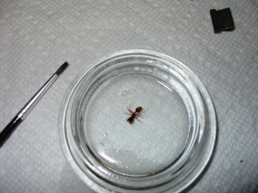
An ant washed into a Syracuse glass for cleaning

If the specimen has been macerated too long, not long enough, or has been otherwise damaged it should be obvious at this point. Whether or not to continue with a damaged or poorly treated specimen is up to the microscopist. An ant that has broken off legs or antennae, or one that is falling apart from too long a maceration can still make a serviceable mount. If the abdomen has been disintegrated (as sometimes happens when macerated too long) consider mounting only the head, mouth parts, antennae, or legs. If the specimen is clearly too thick or still retains its internal organs one can wash it in water and return it to the macerating solution, or start anew with a fresh specimen. Whatever the case, keep written notes on the quality of the specimen had at this point, as it relates to the operations performed on it. It’s one thing to read someones account saying a day or two of macerating is sufficient and something else entirely to know from experience that 48 hours of macerating is too much for one specimen and not enough for an other.

Once satisfied that the specimen is free of debris it must be cleared. Clearing is a simple operation in which the fluid of the specimen is replaced with one which is miscible in the mounting medium to be used. If working with Euparal for instance the clearer used would be Euparal essence or even simple the purest most anhydrous alcohol available. With Canada Balsam (sometimes called xylol Balsam, neutral Balsam, fir Balsam or simply Balsam) one has their choice of clearers, the one selected being largely a matter or preference the procedure is the same whichever is used. Three of the most popular and readily available clearing agents for Balsam are turpentine, xylene, and Clove oil. Of the three Clove oil is the safest to work with (though it is also more expensive and harder to find than either turpentine or xylene) and it is worth noting it has the least offensive scent.

With a fair amount of clearer in a small jar close at hand, remove the specimen from the watch glass using a section lifter, dry camel hair brush, fine forceps or whatever is convenient. Once lifted from the watch glass allow as much alcohol as possible to flow from the specimen without its drying out completely. A small corner of filter paper can be touched to large specimens if necessary. Place the specimen into the jar of clearer. The amount of time required for the clearing agent to penetrate the specimen is dependent on its size and just how well macerated it is. I find that 24 hours is nearly always enough time but have used as little as one or two hours in the past.

Image

Ant in clearer with section lifter and centering card

After 24 hours the clearer should have penetrated the specimen entirely and replaced the alcohol that was used to dehydrate the specimen. If xylene was used as the clearer and it was observed to become milky when the specimen was placed into it then specimen was not fully dehydrated and should be placed into pure alcohol for an hour or so then put into a new dish of clearer. With a fresh and scrupulously clean slide laid out on a centering card the specimen should be removed from the clearer and laid out as desired. It will not be quite so brittle as it was after being taken from alcohol but one must still be exceedingly careful with the delicate appendages.

With the specimen centered on the slide take a small corner of filter paper and leach away any excess clearer clinging to the slide without removing that which wets the specimen. At this stage I find that Clove oil is not only the best smelling clearer but the most forgiving. It will not evaporate nearly as fast as turpentine or xylene and provides some valuable extra time with which to ensure that the specimen is positioned properly. Unfortunately, this also means that specimens produced with Clove oil as the clearer will also require a longer curing period.

Cover slip placement is often treated as a matter of preference but I vigorously oppose that notion. For particular styles of mounting, particular methods of cover slip placement are undoubtedly superior. The best method is however that with which the mounter is able to achieve the best results. In the case of pressed and macerated insect mounts it is easiest to place a drop of mountant on the cover slip and then lower it directly onto the specimen. This method does the most to prevent displacement of the specimen and is the method by which the amount of mountant used is best gauged, an invaluable asses to the novice. One large drop or two small drops from a slender glass rod is about right for most specimens the size of a harvester ant.

Once the cover slip is set one may chose to apply a small amount of pressure with the eraser end of a pencil or a camel hair brush but its not often necessary. Any excess mountant exuded may me cleaned up with bit of filter paper, but take care not to disturb the cover slip. The slide may now be placed in a cool oven or incubator (if one is available) for a few hours to cure. The time required for curing depends on the mountant and clearer used as well as the temperature. If time is of the essence the slide may be warmed over a spirit lamp or Bunsen burner to hasten things along, but superior results are often achieved by simply placing the slide in a case of some sort to keep the dust off and putting it on a shelf or a hot summer time attic for a few weeks. At room temperature a natural Balsam mount with Clove oil clearer can take as long as two months to cure.

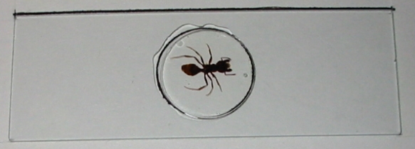
Don’t be discouraged by the waiting time, the longer the period which is available for curing the more opportunity there is for any bubbles in the mountant to work their way out. In some up coming posts I’ll write about putting together a simple slide dryer and ringing a mount of this sort, but for now here’s an ant thats been produced over the course of these blog entries:

Image

Note the air bubble to the right of the lower antenna, and how unconcerned I am about it