The Polarizing Prism
Prior to the advent of thin-film polarizing filters one relied upon specially arranged prisms∗ of a substance known as Iceland spar. This transparent calcite (primarily sourced from Iceland) has the peculiar property of acting as a double refracting filter. There is a certain amount of speculation that Iceland spar is in fact the old Norse sun-stone of legend that permitted navigation based upon the position of the sun even in cloudy conditions. In any case, the ability of the mineral to polarize light, together with the fact that it cleaves easily into rhombs renders it uniquely suitable for the creation of a various forms of prism, two sorts of which were common in polarized light microscopy.
Invented in 1928 by William Nicol, the prism so designated is composed of two portions of a single crystal of Iceland spar cut at precise angles with respect to the axis of their polarization and cemented back together. Once reassembled in accordance with Nicol’s design the double refracting crystal becomes a filter which effectively reduces any light entering it to a single ray of polarized light. A Nicol prism is easily identified because either end of it will show parallel faces of 68°. That the active faces are at an angle makes the Nicol prism less suitable for use as an analyzer and it will be most often found in a polarizer.
Unlike the Nicol prims, a Glan-Thompson prism has both of its active faces at right angles to the axis of polarization. This simple fact makes it well suited to use in an optical system when one needs to maximize the amount of light which will pass through it, and minimize the distance at which it may be placed conveniently over an optical lens. The Glan-Thompson prism acts in much the same way as the Nicol prism, it simply permits a greater percentage of polarized light to pass through.
Antique Apparatus
Historically polarized light microscopy was practiced much as it is today; with either a petrographic microscope constructed specifically for that use, or a pair of accessories that adapt a standard light microscope to the task. Although the precise configuration of the apparatus took may have varied, it generally took one of two forms depending upon the placement of the analyzer. In each form a polarizer was mounted in place of, or beneath the microscopes condenser. One sort used an analyzer that screwed into the objective end of the microscope body after the objective or nosepiece and so introduced the Nicol prism into the optical axis. The second form fit over the end of the microscopes draw tube so that the Nicol prism is introduced over the ocular at the eye-point with a subsequent lens that focuses appropriately. In either form one of the elements will rotate, polarizer or analyzer.
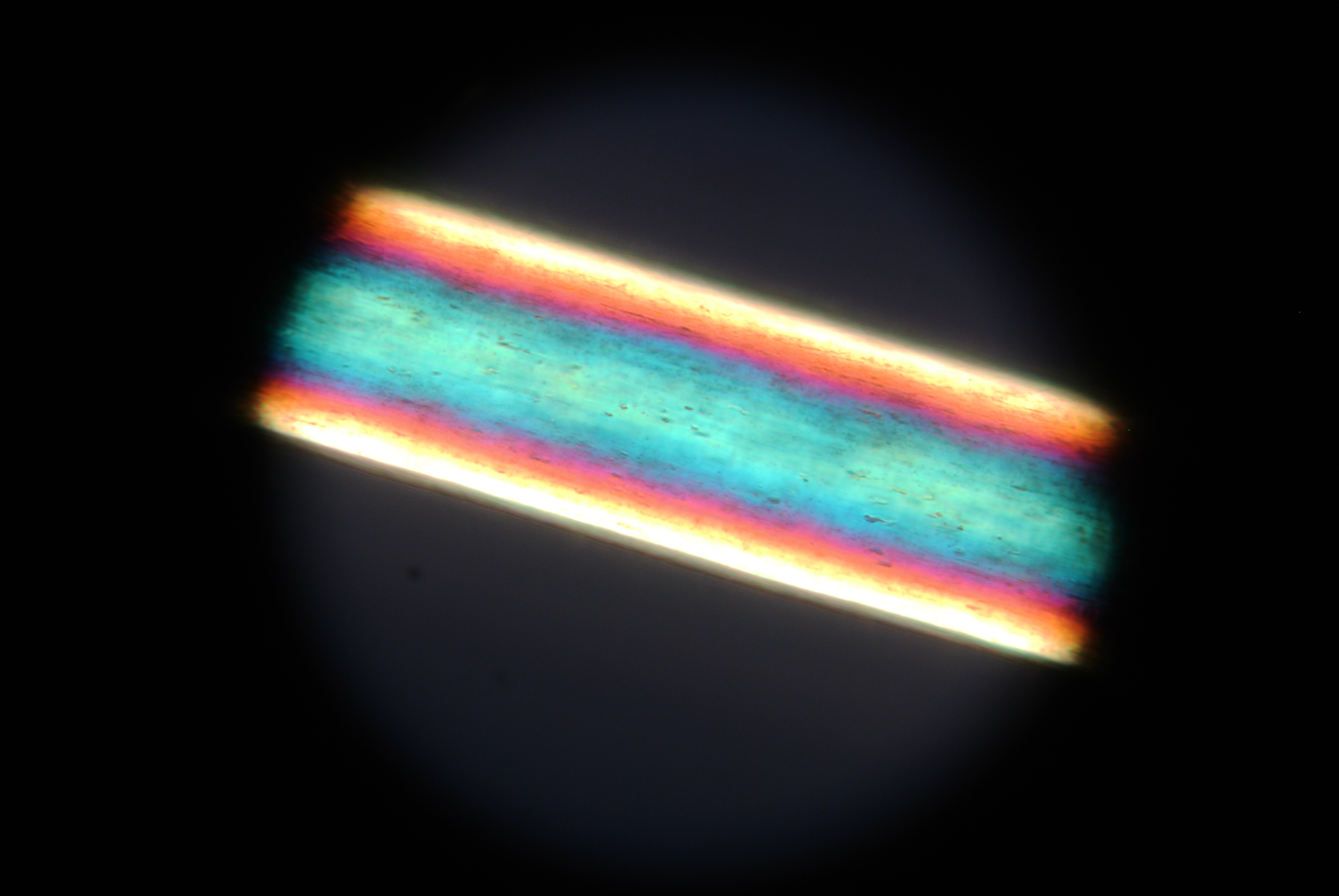
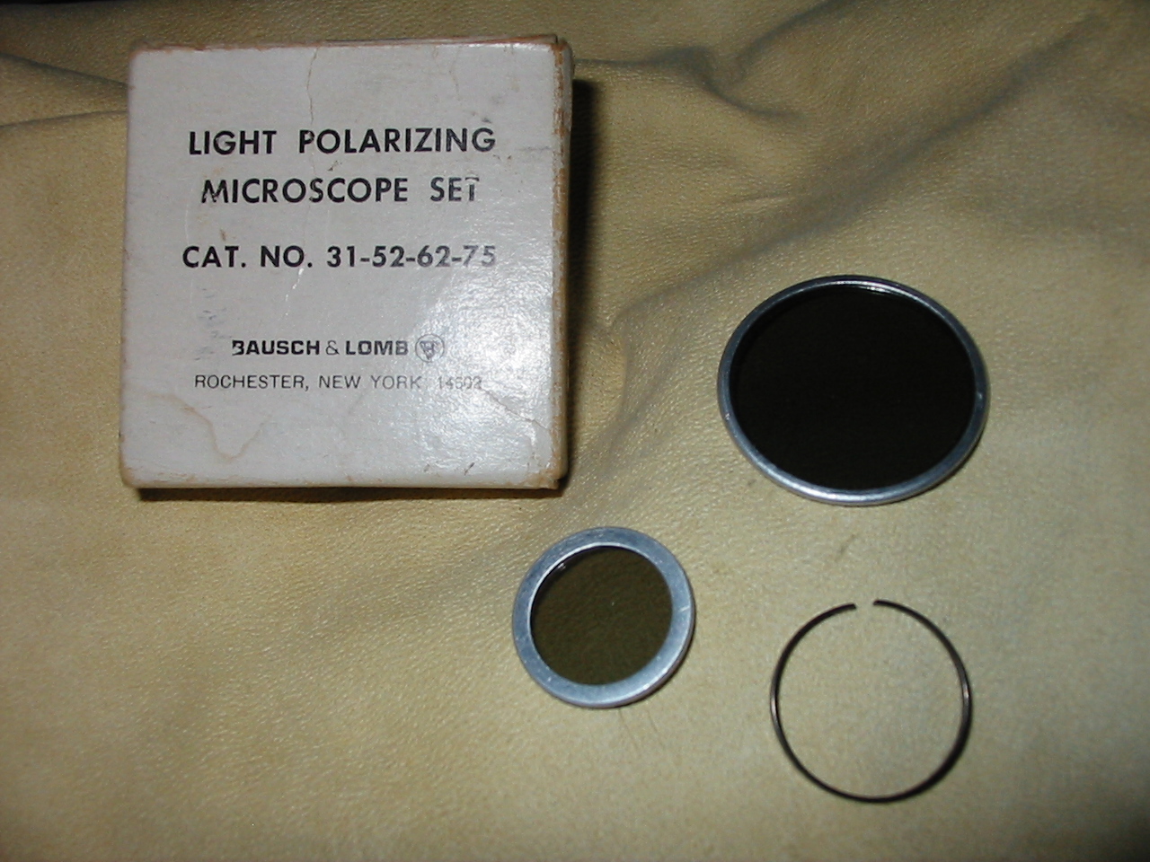
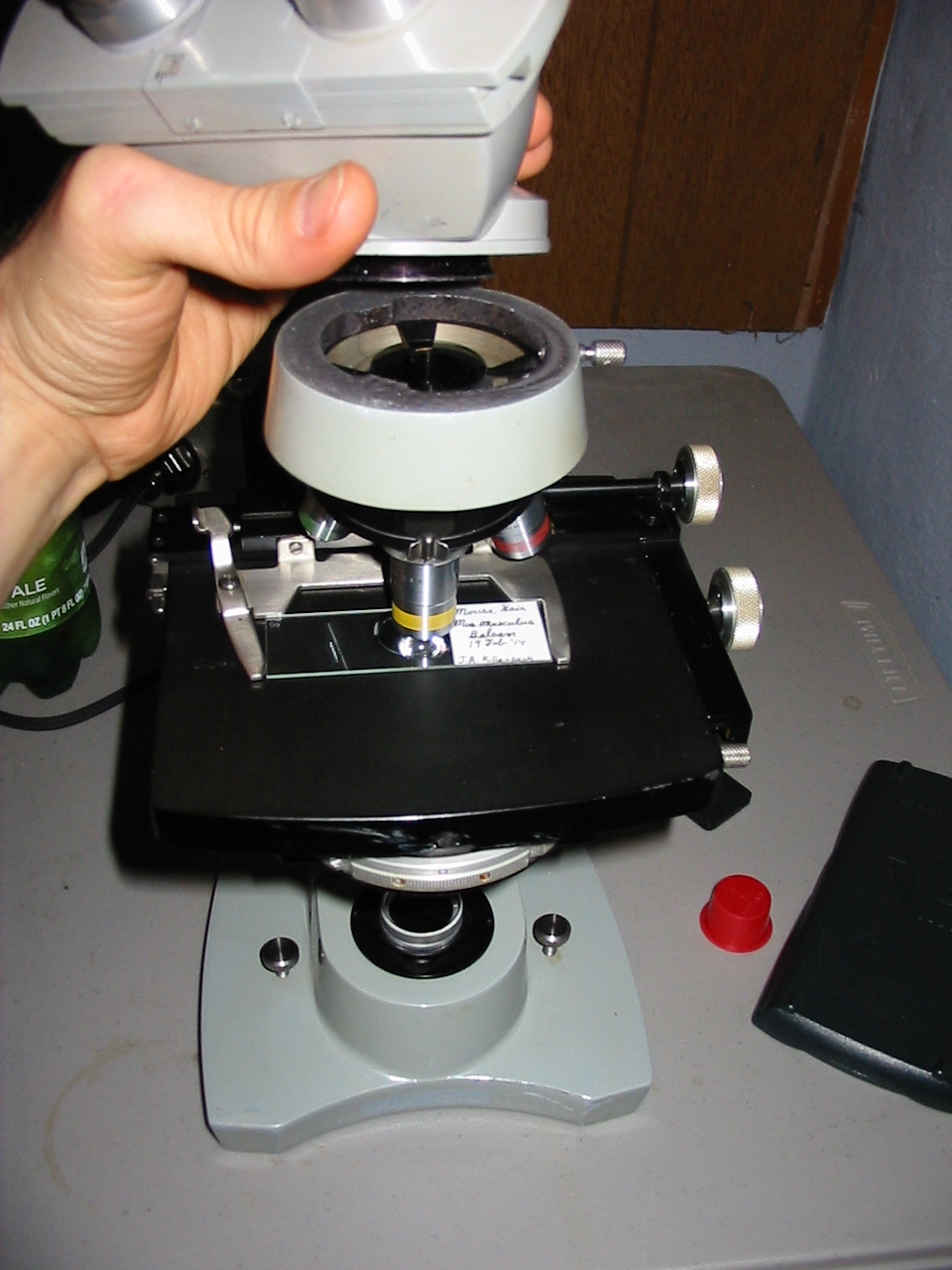
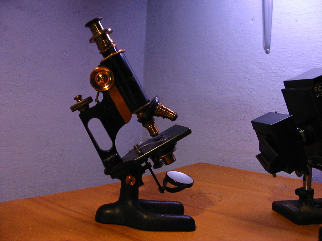
In nearly all forms the rotating component will be inscribed with markings designating the degree of rotation from 0 too 360. Occasionally, the manufacturer may not provide precise or complete markings. Very often the polarizer and analyzer were sold together in a case as either on its own would be of only limited use. Below is an example of a representative Bausch & Lomb polarizing apparatus from the era of the Triple Alliance (1907 – November 1915) first in its case and then fitted to a Bausch & Lomb BH8 dating to c. 1919.

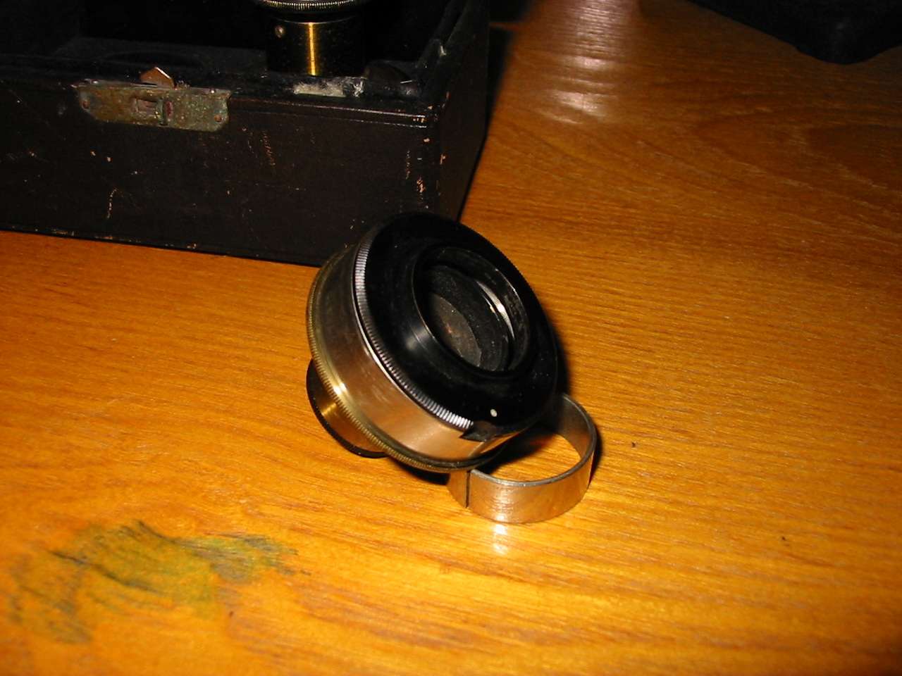
Bausch & Lomb polarizer (left) and analyzer (right).

Polarizing apparatus on period appropriate microscope.

The black surface will face towards the underside of the microscopes stage in use.
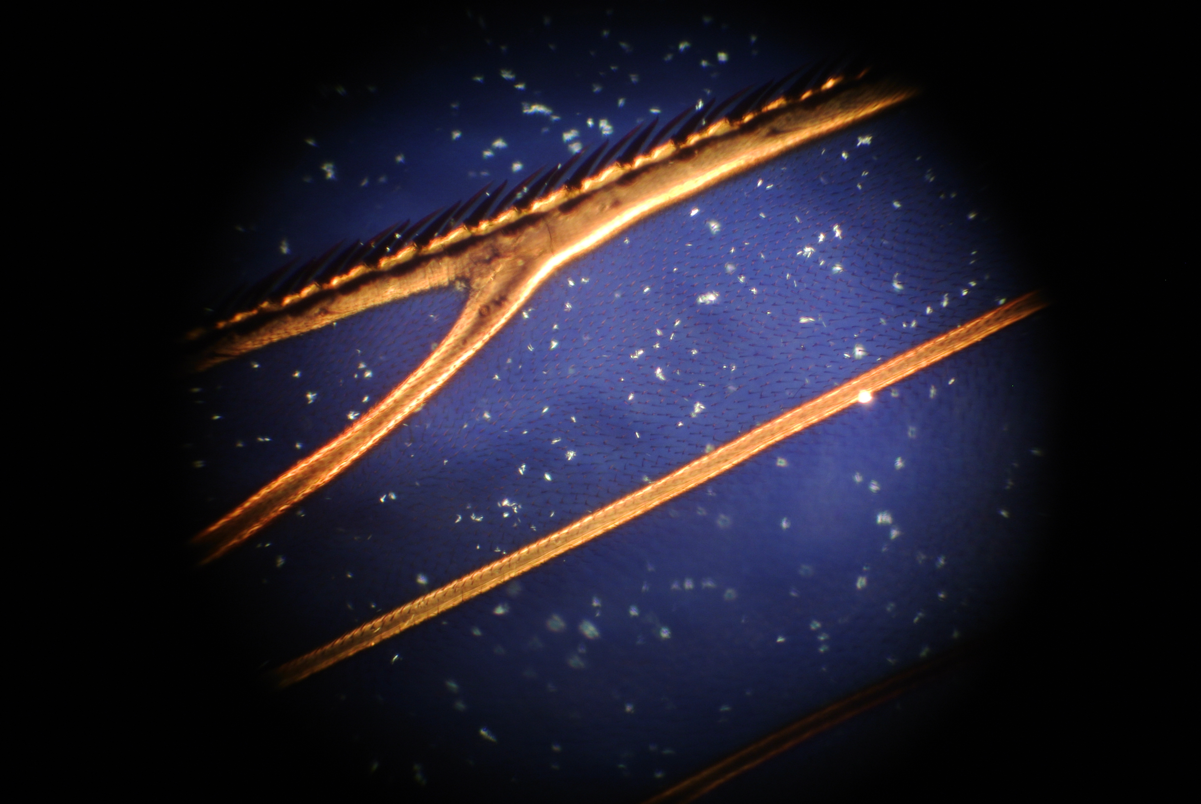
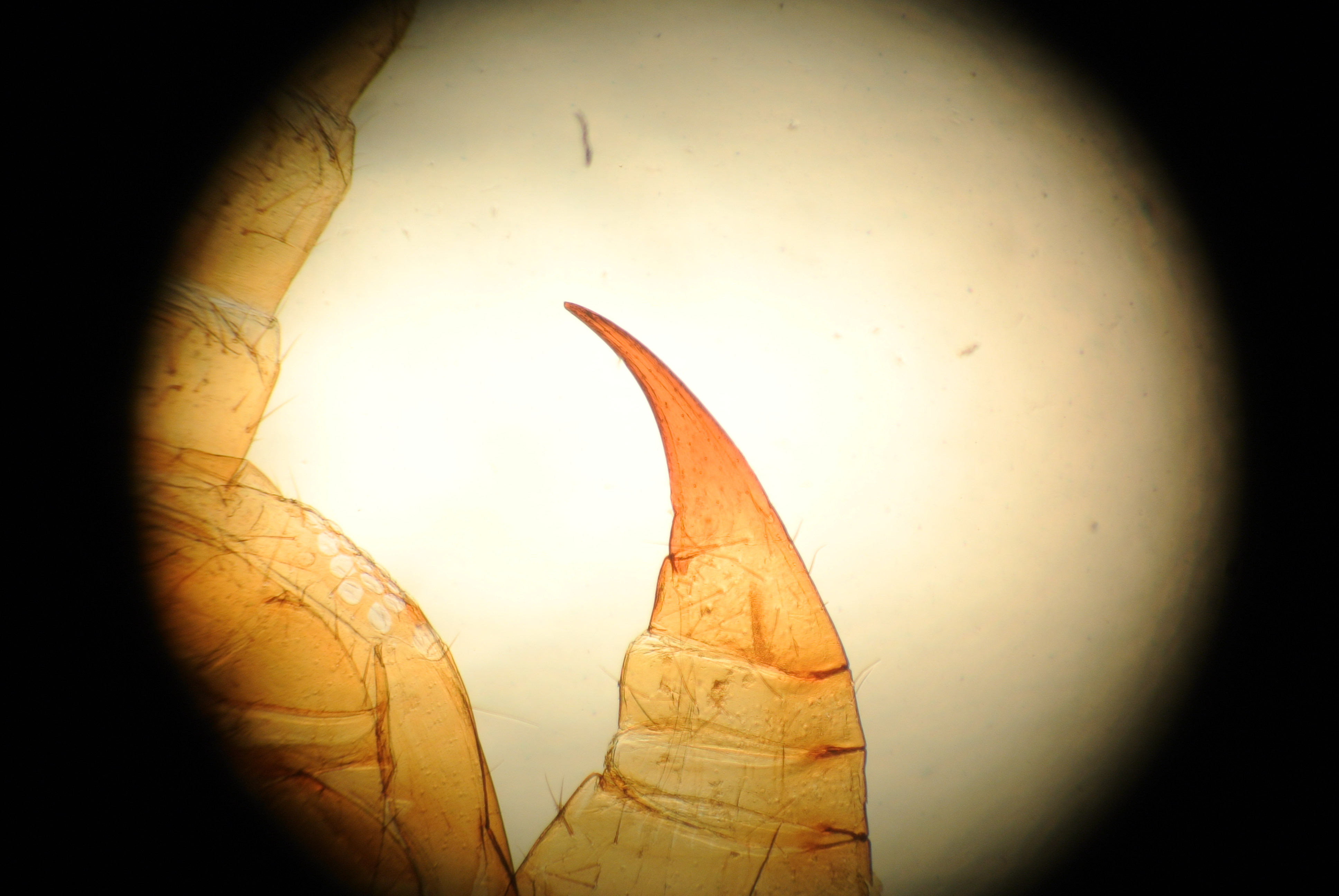
The Polarizer
This example, which carries a Nicol prism of Iceland spar friction fit into a cork, is designed to fit into the substage in place of the microscopes condenser. One will be quick to note that this means one should employ the concave mirror in order to obtain appropriately converging light for illumination. Later varieties of the apparatus constructed along the same lines would feature filters composed of selenite with which one could control the color of the polarized light. Once fitted the condenser adjustment is wracked upwards to bring the Nicol prism as close to the specimen as possible, in this way ensuring the entire field is filled with polarized light.
When mounting a polarizer of this sort (that does not rotate) one should take notice of the orientation of the polarizing prism when placed in position for use. It may be desirable to orient it such that the axis of polarization is not at an odd angle. However one may simply place the polarizer as is convenient and then orient the analyzer.
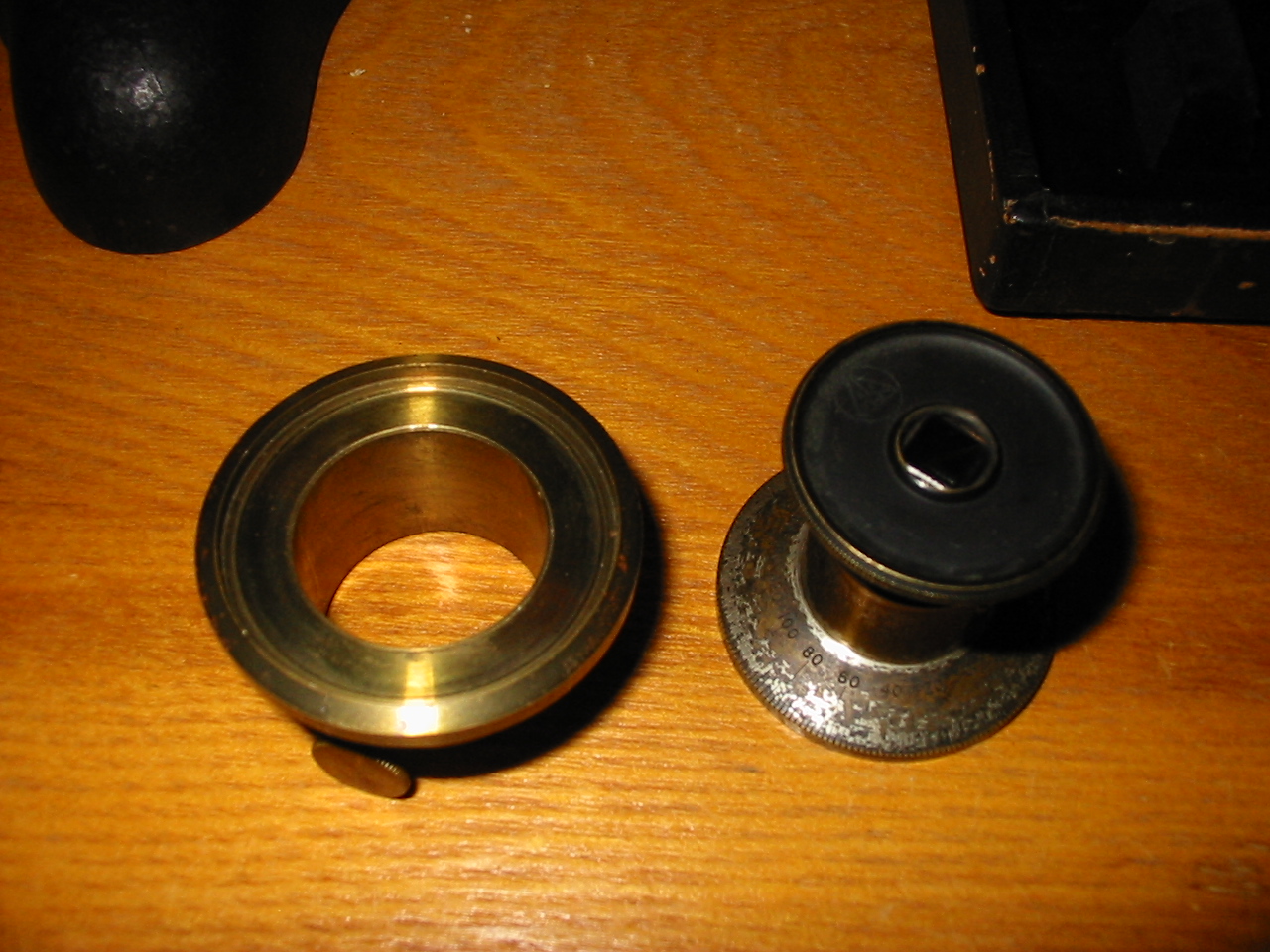
The Analyzer

The left portion contains no optical components and is little more than a mounting collar.
Here, the analyzer being the rotating component, is more complex. Of two portions, the first is fit over the eye-tube of the microscope prior to the placement of an eyepiece and is held in position by a knurled set screw. Once the base portion of the analyzer is fitted to the microscope an eyepiece is inserted and the top portion friction fit into a recess in the unit. Graduated marking around the top portion (which bears the polarizing prism) range from 1 too 360 and show the relative orientation as it is about the optical axis. Due to the limited size of the prism it is not possible to obtain a complete image of the normal field of view with a prism set in a fixed position. For that reason the eyepiece of the polarizer is adjustable in the manner of a draw tube so that an optimum field of view may be had for a given ocular.
The primary advantages of an analyzer of this type are the ease with which the orientation of the analyzer may be read, and the retention of the tube length. Where an analyzer which screws into the body of the microscope between the objective and body tube will add to the overall length of the body tube, this apparatus will not, enabling the markings on the draw tube to be used as normal for coverglass accommodation or other similar adjustments.
Notes:
∗Some of the technical information concerning various varieties of polarizing prims may be found excellently presented in the following pdf available from SPIE, the international society for optics and photonics: PM200.pdf