Light Source Power Supply Alternatives

Get an amazing deal on a stand and have everything you need except the power supply? Don’t leave it on the shelf in the hope of one day converting it for an alternative bulb (LED conversion can be great, it can also be terrible, don’t rush into it) or wait for the day to come when an appropriate transformer turns up, just buy an autotransformer! A suitable autotransformer won’t exactly be cheap but can prove quite economical in the long run, we’ll get to that later, first lets look at what one is, and what’s normally provided. First a little bit about power, lights, and dimmers.

Most of the time, in a residential application that is, light bulbs provide a constant fixed level of brightness (marked on packages in lumens) but generally thought of by the consumer in terms of watts. A watt is a description of energy that is equal to the voltage multiplied by the amperage. The conventional 60w incandescent light bulb may be powered by 120v at half an amp of current, or 12v at 5a. Years ago if one wanted to get a lower level of illumination from an incandescent bulb one used a dimmer switch that contained a variable resistor that limited the voltage which traveled to the bulb the current remained the same. We can see then that the same bulb which provided 60w of illumination at 120v and half an amp would provide 30w at 60v and half an amp. With these type of dimmers the energy that is restricted by the dimmer (30w) is dissipated by the dimmer as heat, no energy is saved, between the dimmer (30w) and the bulb (30w) one is still using 120v and half an amp.

More modern dimmers operate by means of a simple circuit that rapidly turns power traveling to the bulb on and off. It happens so fast that it’s invisible to the eye and with incandescent bulbs the heat held by the filament makes the fluctuation even less noticeable. The advantage of such a dimmer is that there is some minor reduction in power consumption—the reduced wattage output by the bulb is not dissipated by the dimmer as heat. Unfortunately, a by product of such a dimmer is a reduction in the working life of the bulb which should avoided like the plague in the case of frequently difficult to find and expensive to replace microscope illuminator bulbs. Both of these dimmer types, both the old fashioned and modern have one significant flaw for the microscopist—in a word current—but more on that later.

An autotransformer is and electrical voltage transformer of a special sort, functionally a dimmer of the old-fashioned type described above, yet instead of functioning like a resistor it’s a transformer and functions due to induction. Unlike a standard transformer with a primary winding of a particular number of turns and at least one secondary winding of a differing number of turns, an auto transformer has only one winding. In a normal transformer the supply voltage is connected to the primary winding and is output at the secondary at a different voltage that can be calculated with a set of equations.

If the primary has more turns of wire than the secondary the input voltage produces a lower voltage on the secondary it’s called a step down transformer. If the situation is reversed and the primary has fewer turns than the secondary (or the secondary from the first example is used as the primary) it’s a step up transformer and outputs a higher voltage than was input. This is how the old, heavy, wall adapters are able to output 12v even though the socket on the wall provides 120v or 240v.

An autotransformer isn’t automated or automatic, rather it’s so designated for the fact that it is self-transforming. In place of two separate windings a single continuous winding is used for both the primary and secondary. The use of a single winding means an autotransformer rated for a particular input and output voltage will be much smaller than a standard transformer with a primary and a secondary. With most autotransformers the primary and secondary are not in a fixed permanent relationship, but are variable across a given number of steps.  One might just as easily be continuously variable across a range. Most are able to provide an output from significantly lower than the input voltage to a bit over, though others are constructed specifically to provide much higher output voltages than those input. For the purposes here we’ll want an autotransformer which takes a standard input voltage and can output a range from < 1 up to > the input voltage. The practical application of such a device is that an significant number of different bulbs can be run from a single transformer rather than needing a different unit for any particular microscope.

At most hardware stores a standard lamp dimmer can be had for as little as ten dollars, throw in a box in which to mount it and a hardwood base and the whole deal still only just approaches twenty bucks. A secondhand autotransformer might turn up for $50 but one is better off buying new where one can find a 120v autotransformer rated for 20a (of the cheapest sort mind you) for around a hundred, more than five times the cost of a dimmer switch. An autotransformer as described above even if rated for only 10a might weigh as much as twenty or thirty pounds. The reason an autotransformer is preferable has to do with amps and volts. A dimmer switch will only work at the rated voltage, but that’s still not the worst thing about them, after all many student microscopes from the 1960’s and even the 1980’s used a 15w 120v night-light style bulb, it’s a question of current.

The dimmers at the local hardware will at most be rated for 4a, maybe a few for high voltage halogen track lights go as high as 5 or 6a. That’s more than enough for a single incandescent drawing even 2 to 3a at the most. Now, something like the B&L Dynoptic that takes a GE-1634 only draws a single amp, a touch more if over-run to 25v, so a small resistive dimmer would do if installed after a step-down transformer, but it wouldn’t be very efficient. That same bulb could be easily be run by an autotransformer, place a tape mark or two on the control knob to a avoid accidentally feeding it a drastic over voltage and you’re in business.

Where the autotransformer really stands out however, is when it comes to running much older lamps from much different types of illuminators. The first incarnation of the B&L Research Illuminator dates to the early days of electricity and took a range of bulbs from 120vAC to battery based 24vDC home electrification systems that were in use in rural areas for decades before rural electrification ramped up the late 1930’s and post war 1940’s. The second and re-designed Research Illuminator (the model with the rectangular horseshoe base) took as standard a flat filament incandescent that was rated for 18a at 6v. The original power supply for the 100w bulb was about the size of a breadbox and looked and acted much like an early electric space-heater.

The all-metal units contained a large step-down transformer and a multi position switch that would remove one large resistor from series for each step the switch was moved to increase voltage fed to the lamp. It might seem strange that the unit simply didn’t employ a number of secondary windings and so provide a range of voltages with a single component. The use of the resistors made the unit smaller and cheaper to manufacture. Some workers would strip the switched resistor series and replace it with a rheostat (a large type of continuously variable resistor still manufactured but not now in common use) thereby obtaining a continuously variable voltage. In practice the unit was not so different from the device used to run electrical arc illuminators, but had the added benefit of using lower voltage at the output (and using a bulb rather than a cumbersome carbon rod gap).

Using an autotransformer with a B&L Research Illuminator means I don’t have to spring for a supply that runs into the hundreds of dollars even when it does turn up for sale. It additionally means not having to worry about setting fire to the workbench, antique electrical apparatus isn’t known for its safety. Furthermore, autotransformers are always constructed with a fuse, which means that in place of the standard 20a slow-blow fuse (as a rule fuse amperage is identical to the rated current) I can use a fast-blow fuse rated for the amps drawn by the lamp being employed, and add a further level of protection for my bulbs filament.

Beyond that there’s the convince factor. The autotransformer is able to supply the required power for every illuminator I have, everything from the 120v Optilume, to the 115v lamp in the Spherical Illuminator, or down to the 6v halogen in the BalPlan. Even the high intensity 6v 18a (think about that, 18a, the breakers in your utility room are probably only rated for 15a on a lighting circuit!) bulb in the the Research Illuminator. So should we throw out the power supplies we do have in favor of an autotransformer? Of course not, but we should be mindful of it as a safe an effective option for feeding power to a microscope lamp of a variety of illumination systems.

Next time something with pictures, I promise. -K

Light Source Power Supply Anomalies

I’ve been meaning to write about power supplies for some time and a recent exchange reminded me of one of the reasons I was initially prompted to. Anyone who’s frequented this odd little website is aware of my feelings concerning used microscopes; in the words of a breakfast cereal mascot “they’re great!” One thing that is perhaps not so great, completeness. By this I of course refer to the tendency of second hand stands to be somewhat incomplete, particularly as regards light sources and power supplies.

Now the absence of a lamp housing and mount should, as a rule, be considered a deal breaker for a stand that requires one. Very rarely, one might find and recognize a needed lamp housing but the search is liable to be complicated by sellers who are uninformed and so list the item under difficult terms or worse by informed sellers who know the proper terms and therefore the rarity and value of the item. This isn’t about lamp housings though, this is about another component that if missing does not disqualify an otherwise complete or desirable stand from consideration; I write of course of the lamps power supply.

Another enthusiast contacted me with a question about a B&L transformer. As I looked through the manuals for a part number I noticed something interesting. Two versions of the manual for the Dynoptic & DynaZoom had two different sets of published voltages! One version of the manual described the five taps as having the first set of voltages, the other the second. Oddly enough each manual recommended the same GE-1634 lamp.

  1. 1v – 2.2v – 4.5v – 9v -21v
  2. 12v – 14v – 16.5v – 20v – 25v

Admittedly, that’s a 20v bulb, so it’s entirely possible that two version of the transformer were made. Somewhat more unusual is the lack of a specific part number listed in either manual for the transformer itself. B&L at one time or another assigned part numbers to everything from screws to shims, so I’m a little concerned that I only failed in my search because I didn’t read as carefully as I might have. I took a multimeter to each of the corresponding transformers in my collection and both proved to me of the higher voltage varieties. It’s not at all uncommon for a microscope illuminator to provide higher voltage than that for which the bulb is rated. In older textbooks and even on some modern transformers the final tap, or range on continuously variable transformers, is marked as “OV” for over voltage generally called over run. The fact that the second set is so much higher than the first would tend to disqualify the first transformer for photomicrographic work. I’d go so far as to say the binocular heads should not used with the first transformer if one intends to use a daylight filter, and the second shouldn’t be used for visual work without one, or at least a set of neutral density filters.

What I’d like to point out, is not that the published voltages of a transformer may not line up with a transformer that “looks like” the one in hand, or that is available for purchase. Rather, that the important thing is the supply provided by the transformer and its suitability not only for the bulb employed but also the intended use. It’s a simple thing really, and something that might be forgiven for someone who’s only had to deal with common lightbulbs of the sort had at the average home store or hardware. Where then should the enterprising microscopist begin in outfitting a microscopes illumination system? With the correct bulb. The correct bulb will be mechanically compatible with the bulb holder and lamp house as well as of the rated wattage.

I write of wattage because at the beginning the most important and most frequently overlooked characteristic of a bulb is the heat which it will put out. Over high wattages will present a fire hazard, apart from the potential damage to a stand one might also damage the eyes, so do consider the wattage when choosing a replacement bulb. If at all possible always use the bulb recommended by the manufacturer, or a mechanically compatible bulb of lower wattage.

And this weekend, the part I’ve been meaning to write! -K

Opaque Object Microscopy part: IV

6b5a9f08-0fab-42a1-ad1b-51476b3368cc-649-00000095dee1fbdf_file

This last installment will be a look at the B&L STM Electroplater’s Microscope. A refinement on the Standard Teaching line, this Metallurgical microscope is designed for simplicity and easy of use. Superficially it resembles any of the other stands of the ST line, enamel grey with an integral, two-position nose piece, it manages to provide all that is needed and nothing that is not. A single intensity transformer powers a Nicholas style light source that is fixed to the side of the stand just above the nose piece. The light path features a filter holder but is not equipped with either field or aperture diaphragm, rather the light path is permanently restricted to a degree appropriate for the two supplied objectives.

3ca50003-f562-435a-95e7-fbda76ccfc37-649-000000960bbb8e15_file
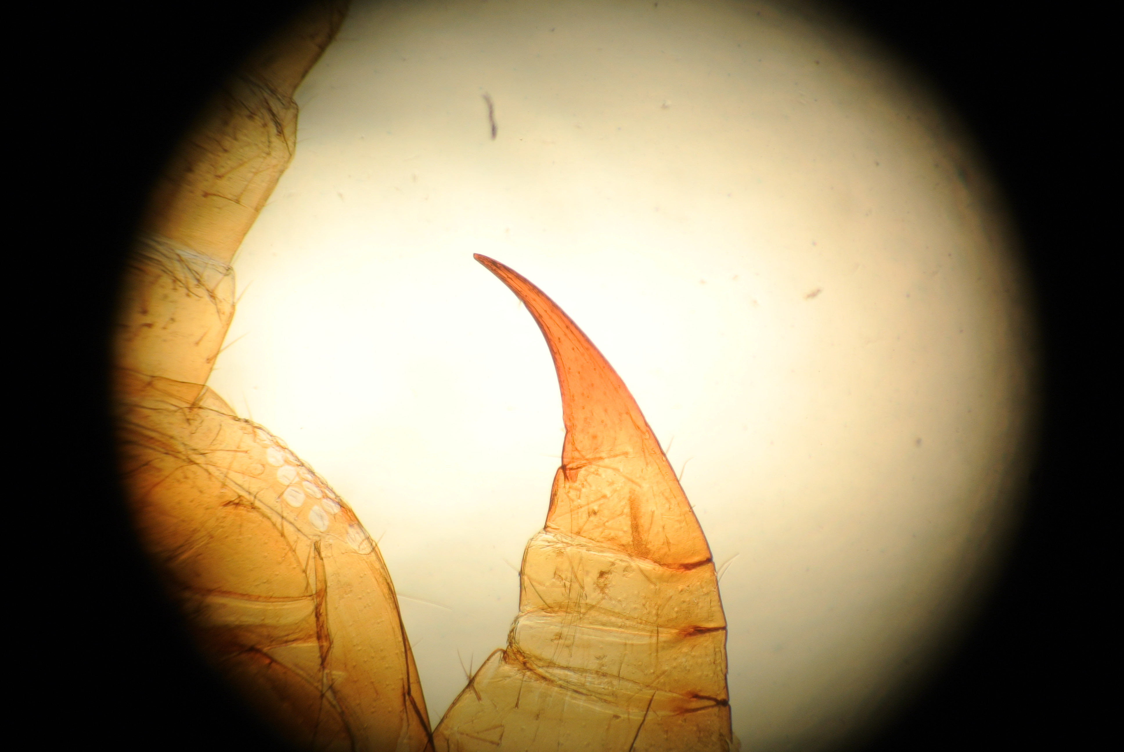
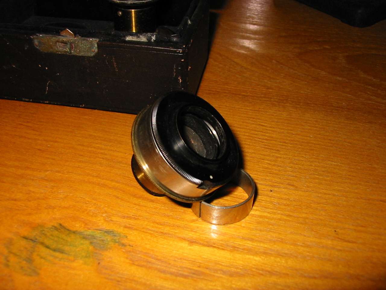
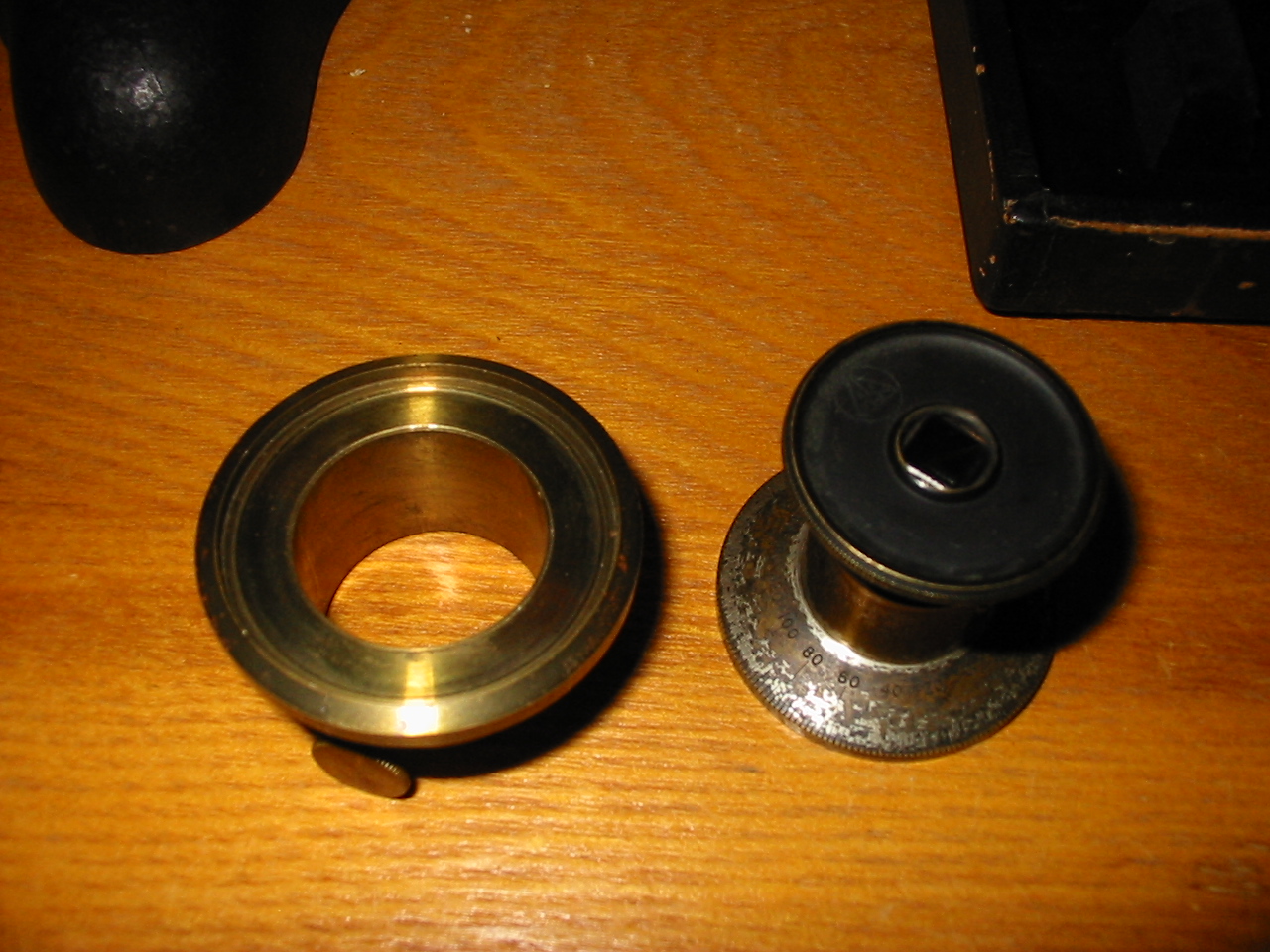
Each objective is of 215mm tube length construction and is corrected for use without any cover glass. One is a low power finder (5x) and the other a higher power (40x). One will quickly notice that neither is of the power one expects to find on a student microscope; 10x and 43x being the usual combination. The reason for this quickly becomes apparent when one calculates powers in consideration of the characteristics of the stand. A 215mm tube length, correction for no cover glass and the nessecity of a short working distance. At right one may see the working distance of the 40x objective.

In place of a standard eyepiece it features a filar micrometer ocular as for most all metallurgical work one would desire the ability to take measurements. In that same vein the fine focus adjustment is graduated as well. Although the stand features an inclination joint, there is no adjustment for the stage and no arrangement to provide for transmitted light work. Internally, the light source is directed downwards by a half silver mirror which is not adjustable without tools. This was no doubt done so that it may be aligned once and may then be employed without a further thought to the matter. When I first acquired this stand the reflector was shattered. No matter, it was easily replaced and enabled me to have this delightful little stand for no more than $40 USD plus shipping!

In the interest of providing a little eye-candy I placed the seemingly polished brass surface of a pocket knife in a bit of putty on the stage. Putty or a specimen holder of the standard sort is recommended for most specimens for the sake of stability. A photomicrographic ocular of 7x power and a Pentax microscope camera adapter was used to take the photomicrographs.

img_0005

Pentax Microscope adapter in place on STM Electroplater’s Microscope

IMGP4472

Low Power

IMGP4473

High Power

In the above images we may observe the compromises made in the STM Electroplater’s Microscope. The low power photomicrograph shows that the apperture size employed in the illumination system is such that slightly less than the entire field is evenly illuminated. In normal visual use with the 10x filar micrometer eyepiece this is only very slightly noticeable. The 7x photomicrographic eyepiece exaggerates the defect because of the larger field of view it provides. It would be possible to artificially crop out the uneven area by using a greater photomicrographic tube extension, but the one I use is perfectly sized as to be parfocal with the eyepieces when employed on a trinocular stand.

In the high power image we will immediately notice how the curved portion of the specimen surface falls out of focus and quickly devolves into a mess of chromatic aberration. This is why flat surface polishing is such an important part of metallurgical microscopy! Luckily enough, the (exceedingly self-congratulatory) microscopist managed to place the specimen such that the two larger scratches (dark marks slightly left of center in the low power photomicrograph) remained in the frame under the higher power objective. Note how the formerly dark high contrast scratches are now fully illuminated and visually interesting.

Next time: Adventures in Large Format Photomicrography! -K

Opaque Object Microscopy part: II

Before looking closely at microscopes which were purpose built for reflected light work it is first imperative that one understands the requirements of such a stand. It must of course allow for some means of illumination, but beyond that there are a few needs that are not so obvious. Consider the compound transmitted light microscope, several aspects of it’s construction are dictated by the optical properties of human vision, a substantial number of others are dictated around changeable constants that are functionally arbitrary. A microscope slide and cover slip that is of a given thickness greatly simplifies the construction of an optical system that will provide an ideal image with minimal and known defects. Furthermore, it dictates that all specimens will be of a consistent and narrowly variable thickness.

Any microscope that needs to accommodate opaque objects will either have to account for the need to examine specimens of unknown thickness or be considered specialized. It need not be overly complex, one could make use of a stand having a significant range of motion in its coarse focus, or possessing a means of modifying its base working distance-as one finds on many stereo microscopes.. A further option would be to articulate the stage such that it may further enlarge the accommodation of the coarse focus. This is a simple mechanical alteration to an otherwise standard microscope foot; as a condenser is unnecessary, the stage is for all intents and purposes mounted to the condenser mount. An inverted microscope forgoes this need entirely by radically re-configuring the entire apparatus, a good investment if only one microscope is liable to be acquired, but it’s worth noting that inverted microscopes are in general far less common on the second hand market and consistently more expensive.

It is also required that the microscope provide for the specialized optics of a reflected light system, namely the light source. In the initial post we saw the difficulty of using a light source external to the image forming optical axis. It is therefore required that the illumination system be congruent with the optical axis. This requires that there will be some additional apparatus placed somewhere in the optical axis, by convention it is generally placed outside of the body, between the nose-piece and the end of the body tube. Whether this is dictated by optics rather than mechanics (or the economics of manufacturing) is unimportant, the result is the same.

At a point in the optical column of the microscope a high intensity light source is introduced. In every example of which I am aware this light source is situated perpendicular to the axis. It is suitably condensed and often fitted with a pair of iris diaphragms (a field diaphragm and condenser diaphragm) as well as filter carrier before being directed down towards the objective via a reflecting surface. A prism or half silver mirror is the usual method; often both are available with the ideal choice being contingent upon specimen and objective.

The actual construction of the reflector is related to the properties of the objective, with all parts involved being of a number of mechanical types. All of the differences in the system of illumination are chiefly concerned with the path of light. There exist two primary types: coaxial and vertical. It’s confusing because few operators, and even manufacturers are careful with their terminology.

Both coaxial and vertical illumination are methods of reflected light microscopy, and coaxial is by definition vertical while vertical is not necessarily coaxial. Coaxial illumination is so called because the path of the light source shares its axis with the path of the image forming rays. The poor mans coaxial illuminator is a flashlight held to one eyepiece of a binocular stand while the other is used for viewing-authors note: don’t do it! The axis of illumination and image formation are one and the same. Vertical illumination is a story of two axes where each is distinct but parallel. The most common type of vertical illuminator is able to provide both methods, but the quality of the coaxial illumination is often inferior when compared to modern outfits designed for coaxial illumination.

Without bothering to get in to dark-field (yes, there are dark field objectives for reflected light work) there are two types of objective one will encounter. The first is essentially no different from any standard objective, excepting of course for differences in the common powers, corrections, and other properties best left for later. The second, and more complex type, is designed to work with a particular type of light source. This second type (which I have always thought of as metallurgical as that is how the BalPlan microscope line of B&L designated them and they were the first I used) caries within its body a transparent glass bushing which extends from the mount to the object lens, surrounding totally and supporting the lenses of the objective. This glass pipe is little more than a means of placing a ring of evenly diffused light on the specimen in a place where the objective itself would obscure other sources. Properly arranged, it is an excellent system and dispenses with much of the glare one will find in poorly aligned coaxial or even vertical systems.

There, next time: photos! -K

Opaque Object Microscopy part: I

I think at this point I’ve been away long enough that this may qualify more as a return from the dead than a return from a hiatus. -K
Most of what anyone at the level of a hobbyist is going to be looking at with a microscope is going to be what is convenient. Now, this is not meant as an indictment, merely a truthful commentary. For the bulk of those with a microscope this is going to mean that what one is going to be looking at is dictated first, by the microscope which is available, and only after by ones interest. When conditions allow this translates to transparent objects for the compound microscope and large opaque objects for the stereo microscope. There are, thankfully, limitless opportunities for the indulgence of ones interest regardless of the microscope which is available.

The next few posts will focus on a category of microscope which is rather less common but is specialized for a particular variety of specimen. The particular type of microscope is rather less common, and one could speculate endlessly on the reasons for this. This microscopist is of the opinion that the reason for this is in general attributable to its being far harder to prepare specimens for a reflected light microscope, than to settle for lower magnification and use a stereo microscope. However, there are a variety of applications for which one will find the power of a stereo microscope lacking. One is then left with the prospect of attempting to so treat the specimen as to render it suitable for transmitted light microscopy, or of finding some way of providing suitable lighting and using a standard compound microscope. Anyone who has attempted to observe an opaque object at high power will understand the difficulty of providing for adequate illumination.

For the sake of completeness, here are the logistics when one is forced to make use of a standard compound light microscope for reflected light work. One might first make use of some small and high intensity light source, employing it in such a way that the termination of the visual optical axis is brightly lit. This is actually surprisingly simple in the present day when an LED flashlight the size of a shotgun cartridge is brighter than any oil lamp. After oil lamps gave way to electric lamps the microscopist was required to somehow retrofit a standard lamp bulb so that it would provide a bright beam of light with no errant brightness.

There was also the possibility of purchasing a small bright light source such as a Nicholas lamp. Although those were surprisingly expensive in their day, they are quite economical now and widely available second hand provided one is willing to type a few searches. Before getting to much farther off topic, do consider picking up a Nicholas illuminator. Color temperature aside, the tight beam is well corrected and the arm most are fitted with is a great asset. Working with a Nicholas lamp and a compound microscope, we will quickly see why this method is far from ideal.

IMGP0005

Poorly set up.

In the above image we can see that a light source is set up sufficient to permit the specimen (here the engraved body of a pocket knife) to be brightly illuminated to the naked eye. There is enough working distance that no significant difficulty was involved in setting it up. A quick look through the eyepieces will immediately demonstrate that this set up is not only far from ideal, but entirely unsuitable. The light source is a painfully bright halogen bulb but the view from the oculars is quite dim, contrast is excessive, and there are visible color fringes even though the lowest powered objective (here a 30mm EF/3.5x achromat) is being employed. Some of these defects can be corrected even in this compromise set up.

IMGP0010

Ideal compromise set up.

In the above image is shown an exaggerated ideal arrangement of the available resources. If one takes the stage for a plain, and draws a vertical line along the visual optical axis the light from the illuminator should be arranged so as to be as at the most acute angle to the optical axis possible. This will go a long way to limiting the extremes of contrast and removing the color fringes. It will similarly  render the specimen as bright as possible under the present conditions.

It may not be immediately apparent but working distance is the limiting factor here. As soon as one moves beyond the 10mm or so that one is afforded by a standard 16mm (10x if you’re more comfortable with magnification than equivalent focus) objective the few working distance of a 4mm (43x) objective is far to short, even that of a rather less common 8mm (21x) objective will be much to short for all but the most intrepid of operators. Then, should illumination be secure one will be presented with a view of such poor quality that the effort is entirely wasted.

Next up… vertical illumination.

XN/Pol vs BF

Pardon?

If the cryptic title of today’s post seems bizarre please remember that for most people microscopy is limited to only one sort: light microscopy. Further one could say that for most people light microscopy is limited to one particular sort: bright field. For the last few posts we’ve been getting into polarized light microscopy in a very general way and with that in mind the obscure little title should make perfect sense.

XN is still used in some papers by authors who wish to refer immediately to crossed Nicol prisms, or crossed polaraizer and analyzer. In practice one may rapidly find the point at which their polarizer and analyzer are crossed by turning one or the other until the light which is seen to pass between the two is at its lowest ebb.

XN in Action

The following photomicrographs were all taken with trinocular AO Spencer microscope using a Nikon 1 J1 consumer grade digital camera fitted with a Nikon 1 to c-mount adapter and c-mount to 23.3mm microscope eyepiece tube adapter. The polarizing apparatus was constructed out of two small discs of polarizing film which cost only $5.00 with shipping. If a full sized image is desired one need only click the image but be warned they are several MB in size. First will be shown the specimen in bright field, followed by the object under XN.

A human hair.

A human hair.

The same hair.

The same hair.

A mouse hair.

A mouse hair.

The same hair.

The same hair.

Portion of a fly wing.

Portion of a fly wing.

The same flys wing.

The same flys wing.

A centipedes forcipule.

A centipedes forcipule.

DSC_0998

The forcipule again.

Many natural fibers, everything from cotton to the hair on ones head, are strongly birefringent. Different forms of fiber will show differently under crossed pols. A motivated individual can discern much from a hair without resorting to such destructive methods as scale casting.

Insects may be surprisingly dull subjects for polarized light and the process may do little but reveal how much dust was remaining on the specimen, as in the case of a hastily mounted flies wing which was collected from a disused attic. At times one may find with surprise that small portions are powerfully birefringent, as in the case of the hardened, venomous, forcipule of the garden centipede pictured above. Frequently only the mouth parts of a specimen will show double refraction. This simple fact can be immensely helpful when trying to identify the mouth parts accurately in whole mounts, especially when optical sectioning is insufficient.

One of these days I’ll have to put up a video of some chemical crystals under XN, stay tuned! -K

Simple Polaroid-based Polarizing Apparatus

The Polaroid

One is going to need a quantity of polarizing film (polaroid) for any easily constructed polarizing apparatus. Fortunately, the material is inexpensive and readily available from any number of sources online. When seeking the material for construction one should purchase linear polarizing polaroid rather than the circularly polarizing filters common in photography. Do not hope to luck out with a bargain by purchasing the sort of polarizing film sold for use with LCD screen repair and refurbishment, it will not prove suitable.

The size of the film purchased will vary depending on the sort of apparatus which is planned but in most cases a small piece of five square centimeters (two square inches) is enough. One shouldn’t feel obligated to purchase expensive polaroid whether that expense is attributed to the supposed quality of the film (the perfectness of the polarization) or its thickness or any protective coating. Very often one may have the option to purchase polaroid in varying thickness, and the thicker film is useful for applications that require a large self-supporting filter, but in many cases the thinner product is preferable simply because it is easier to work with.

The Example

Not one to miss out on a potential market, Bausch & Lomb marketed a simple polarizing apparatus for users who did not require (or have the budget for) the more complex prism-based variety. Below is seen an exceedingly simple set composed of polarizing film set into light metal frames. One portion is a 21mm disc and the other is of 32mm, a split ring retainer is included. The concise instructions on the reverse of the box direct the user to install the smaller disc in a standard eyepiece by separating the components of the eyepiece so that the disc may rest upon the eyepiece diaphragm. The eyepiece itself then becomes the analyzer which is in this instance the rotating component. The 32mm disc is sized to be compatible with filters used in most substages and serves as the polarizer.

Simple commercial example of a type anyone can produce.

Simple commercial example of a type anyone can produce.

Right away one can see that an essentially identical set may be produced for just a few dollars. If one is loath to risk the cleanliness of an ocular by separating the components to insert the analyzer, a cap may be fashioned that holds the polaroid and fits above the microscopes eyepiece. It will work in precisely the same fashion and has the advantage of not requiring an ocular be put aside for polarizing work only. Regrettably, one will recognize very quickly that such a set, whether the analyzer is integrated with an ocular or placed over it, will not work effectively on a binocular or trinocular microscope.

Special Considerations

For microscopes equipped with binocular or trinocular heads, one should place the analyzer in a location such that it acts upon the light prior to that light being sent into the eyepiece or photo tubes. Fortunately it is often a simple matter to remove the microscopes head and place the analyzer within. Once the analyzer is positioned one must look to the way in which the polarizer may be accommodated. In most cases it is not advisable to use a 32mm disc placed in the substage filter holder simply because rotating it once positioned is inconvenient. Very often only a small effort need be expended to create a holder that may be placed in the substage to facilitate rotating the polarizer. In any case one should endeavor to arrange polarizer and analyzer so that both may be quickly removed or installed, and one of the two is rotatable.

Improvised polarizer and analyzer in place on AO Spencer microscope

Improvised polarizer and analyzer in place on AO Spencer microscope

In the photograph at right one can see that a simple disk of polarizing film has been placed intermediate to the objective turret and trinocular head of this AO Spencer Microstar microscope to serve as the analyzer. A rotating polarizer has been constructed from a plastic film canister lid and aluminum screw cap, it fits conveniently in the 32mm filter recess of the microscopes integrated illuminator. By virtue of the microscopes construction only one finger screw needs to be loosened to remove the head and place the analyzer. For ease of handling, and so that it may serve double duty the analyzer was cut to a size of 32mm and may be used as the polarizer when placed in the substage filter holder of a monocular microscope. One should note that the polarizer is of a size that no light may pass out of the integrated illuminator that does not pass through the polarizer.

Next time: eye-candy! A few nice photomicrographs of slides with bright-filed and polarized light. -K

Polarized Light Microscopy Apparatus

The Polarizing Prism

Prior to the advent of thin-film polarizing filters one relied upon specially arranged prisms of a substance known as Iceland spar. This transparent calcite (primarily sourced from Iceland) has the peculiar property of acting as a double refracting filter. There is a certain amount of speculation that Iceland spar is in fact the old Norse sun-stone of legend that permitted navigation based upon the position of the sun even in cloudy conditions. In any case, the ability of the mineral to polarize light, together with the fact that it cleaves easily into rhombs renders it uniquely suitable for the creation of a various forms of prism, two sorts of which were common in polarized light microscopy.

Invented in 1928 by William Nicol, the prism so designated is composed of two portions of a single crystal of Iceland spar cut at precise angles with respect to the axis of their polarization and cemented back together. Once reassembled in accordance with Nicol’s design the double refracting crystal becomes a filter which effectively reduces any light entering it to a single ray of polarized light. A Nicol prism is easily identified because either end of it will show parallel faces of 68°. That the active faces are at an angle makes the Nicol prism less suitable for use as an analyzer and it will be most often found in a polarizer.

Unlike the Nicol prims, a Glan-Thompson prism has both of its active faces at right angles to the axis of polarization. This simple fact makes it well suited to use in an optical system when one needs to maximize the amount of light which will pass through it, and minimize the distance at which it may be placed conveniently over an optical lens. The Glan-Thompson prism acts in much the same way as the Nicol prism, it simply permits a greater percentage of polarized light to pass through.

Antique Apparatus

Historically polarized light microscopy was practiced much as it is today; with either a petrographic microscope constructed specifically for that use, or a pair of accessories that adapt a standard light microscope to the task. Although the precise configuration of the apparatus took may have varied, it generally took one of two forms depending upon the placement of the analyzer. In each form a polarizer was mounted in place of, or beneath the microscopes condenser. One sort used an analyzer that screwed into the objective end of the microscope body after the objective or nosepiece and so introduced the Nicol prism into the optical axis. The second form fit over the end of the microscopes draw tube so that the Nicol prism is introduced over the ocular at the eye-point with a subsequent lens that focuses appropriately. In either form one of the elements will rotate, polarizer or analyzer.

In nearly all forms the rotating component will be inscribed with markings designating the degree of rotation from 0 too 360. Occasionally, the manufacturer may not provide precise or complete markings. Very often the polarizer and analyzer were sold together in a case as either on its own would be of only limited use. Below is an example of a representative Bausch & Lomb polarizing apparatus from the era of the Triple Alliance (1907 – November 1915) first in its case and then fitted to a Bausch & Lomb BH8 dating to c. 1919.

Bausch & Lomb polarizer (left) and analyzer (right).

Bausch & Lomb polarizer (left) and analyzer (right).

Polarizing apparatus on period appropriate microscope.

Polarizing apparatus on period appropriate microscope.

The black surface will face towards the underside of the microscopes stage in use.

The black surface will face towards the underside of the microscopes stage in use.

The Polarizer

This example, which carries a Nicol prism of Iceland spar friction fit into a cork, is designed to fit into the substage in place of the microscopes condenser. One will be quick to note that this means one should employ the concave mirror in order to obtain appropriately converging light for illumination. Later varieties of the apparatus constructed along the same lines would feature filters composed of selenite with which one could control the color of the polarized light.  Once fitted the condenser adjustment is wracked upwards to bring the Nicol prism as close to the specimen as possible, in this way ensuring the entire field is filled with polarized light.

When mounting a polarizer of this sort (that does not rotate) one should take notice of the orientation of the polarizing prism when placed in position for use. It may be desirable to orient it such that the axis of polarization is not at an odd angle. However one may simply place the polarizer as is convenient and then orient the analyzer.

The Analyzer

The left portion contains no optical components and is little more than a mounting collar.

The left portion contains no optical components and is little more than a mounting collar.

Here, the analyzer being the rotating component, is more complex. Of two portions, the first is fit over the eye-tube of the microscope prior to the placement of an eyepiece and is held in position by a knurled set screw. Once the base portion of the analyzer is fitted to the microscope an eyepiece is inserted and the top portion friction fit into a recess in the unit. Graduated marking around the top portion (which bears the polarizing prism) range from 1 too 360 and show the relative orientation as it is about the optical axis. Due to the limited size of the prism it is not possible to obtain a complete image of the normal field of view with a prism set in a fixed position. For that reason the eyepiece of the polarizer is adjustable in the manner of a draw tube so that an optimum field of view may be had for a given ocular.

The primary advantages of an analyzer of this type are the ease with which the orientation of the analyzer may be read, and the retention of the tube length. Where an analyzer which screws into the body of the microscope between the objective and body tube will add to the overall length of the body tube, this apparatus will not, enabling the markings on the draw tube to be used as normal for coverglass accommodation or other similar adjustments.

Notes:

∗Some of the technical information concerning various varieties of polarizing prims may be found excellently presented in the following pdf available from SPIE, the international society for optics and photonics: PM200.pdf

Elucidating Illuminators: IV

Ray Diagrams

By far the most complicated of the bright field illumination methods, it wouldn’t do to continue on about Köhler illumination without first explaining what sets it apart from critical illumination. In the previous post we found that critical illumination places an image of the light source in the field of view had at the eyepiece, Köhler illumination does not. The reason that Köhler illumination does not put an image of the light source in the eyepiece image (the image plane of the specimen) is that the path of the illuminating rays of light differs substantially from that of the image forming rays of light. It may seem strange to think of at first, but it will become quite clear after a bit of explanation. If it does not seem straight forward, refer back when setting up for Köhler illumination and things will no doubt fall into place.

Above: Image forming rays. Below: Illuminating rays.

Above: Image forming rays. Below: Illuminating rays.

In the rough sketch above we can see the path of image forming rays, and the path of illuminating rays. For interested parties unused to the conventions of ray diagrams, it will suffice to say that where the rays intersect an image is formed. Looking specifically to the image forming rays of each diagram we can see where an image of the light source is formed: at the diaphragm of the lamp, at the diaphragm of the substage condenser, at the rear focal place (rear lens) of the objective, and within the lens of the observers eye. One will also note that as the image of the lamp is formed at the same location as a diaphragm, that diaphram will likewise be in focus with the light source image. For this reason when set up for Köhler illumination we should be able to observe an image of the light source on the substage diaphragm and an image of the substage diaphragm together with that of the light source at the back lens of the objective. We also can see that an image of the lamps diaphragm will be formed at the image plane of the specimen, and again where it will be magnified further by the eyepiece. For this reason, when focused on the specimen, we should be able to stop down the lamps diaphragm and see the edges of it in focus with the specimen.

If a moment is taken to observe the eye in each part of the above image two important things can be observed; even if not readily apparent in the crude diagram. The path of the image forming rays shows that an image of the specimen converges on the fovea, while the image of the light source does not. Looking to the portion of the eye that is filled by the light forming rays, it is seen that an image of the light source is formed at the iris, and the rays diverge across the retina.

Köhler Illumination

Before getting into the set up process a few important notes are necessary. A filament image is apt to be extremely brilliant, take care to lower the intensity of the light appropriately. Do not fall into the misconception that light sources equipped with a permanent ground glass filter or opal bulb are not able to provide Köhler illumination. It will just be very difficult to determine if the light source is in focus on the field diaphragm of the lamp and substage diaphragm. This difficulty may generally be overcome by the introduction of a disturbance (a pencil mark or foil point) on the bulb or ground glass.

  1. Arrange the bulb of the illuminator in conjunction with the condenser system of the lamp so that an image of the light source is in focus in the plane of the illuminators condenser. Adjustments depend on those available with the illuminator itself, but determining focus is generally a simply matter of introducing a ground glass or scrap of paper at the diaphragm opening.
  2. Open the lamps field diaphragm and stop down the diaphragm of the substage condenser.
  3. Position the illuminator so that an image of the light source (generally the lamp filament) may be seen in focus on the surface of the microscopes substage condenser. If set up for horizontal use it is exceedingly simple. When working vertically or at a comfortable incline it seems very difficult until, one takes a small mirror and positions it to view the substage diaphragm easily when standing ready at the microscope.
  4. Open the substage diaphragm and focus a well stained smear or thin section of uniform thickness on the stage using a 16mm objective and 10x eyepiece.
  5. Adjust the field diaphragm of the illuminator until it is seen in the field of view had at the microscopes eyepiece.
  6. Adjust the substage up or down until the field diaphragm is seen in focus within the image plane of the specimen.
  7. Open the field diaphragm of the illuminator until it is no long seen at at the microscopes eyepiece.
  8. Remove the microscopes eyepiece and sight down the body tube from a distance of ten inches (250mm).
  9. Adjust the substage condenser diaphragm until the brightly lit back lens of the objective is just seen to be obscured.
  10. Replace the eyepiece.
  11. Repeat steps 5-10 whenever the objective is changed.

It’s worth noting that when sighting down the body tube for step 8 one should be able to see a clear image of the light source. One should also be able to image the field diaphragm and substage diaphragm, which makes this step a wonderful time to stop and center the illuminator and substage condenser. At step 9 it may be necessary to obscure more or less of the back lens to provide for optimal contrast; from 25-33% is the recommended amount which should be obscured. Every increase in contrast beyond that which allows for the microscopist to better discern detail is still an theoretical decrease in numerical aperture and should be avoided if increased contrast is not revealing additional detail.

Examples

Filament image as seen in mirror.

Filament image as seen in mirror.

In the photograph at left, the arrangement of a small mirror for observing the filament image as projected onto the underside of the substage condenser may be seen. In order to better illustrate the situation a bulb with a single long coiled filament was used. For microscopy it is often better to use a bulb with multiple filaments (or an opal bulb or diffuser) so that the entire underside of the substage diaphragm may be filled with light; doing so will result in a more uniformly lit field.

Field diaphragm of the illuminator

Field diaphragm of the illuminator

At right the image of the the very constricted field diaphragm may be seen. In practice it will not be necessary to stop down the diaphragm to such an extent. The color fringes seen around the diaphragm opening are evidence of the fact the the microscope condenser is of the chromatic (Abbe) type. The fact that the color fringe is of different colors on the left and right sides is proof that the illumination is not entirely axial. For critical work it would be advisable to take the time to properly align both the filament to the lamps condenser and the mirror to the same so that the color fringes are concentric to each other.

Escherichia coli with 16mm objective and 10x ocular.

Escherichia coli with 16mm objective and 10x ocular.

In the above photomicrograph we see that although the use of a single coil filament bulb produces a bright image, it is not uniform. Note in particular the right margin of the image where the coils of the filament are most apparent. Despite the limited size of the single coil filament, and the large field of view provided by the 16mm objective, it is worth pointing out that the central portion of the image is well lit by the commonly available bulb. There is no need to rush out and buy an expensive specialty bulb.

Notes:

∗Most introductory courses in physics will cover the basics of ray diagrams as they relate to the use of mirrors and lenses. A simple web search will provide ample explanations and illustrations.

†It can be difficult for some people to view the rear lens of the objective unassisted. To provide assistance one can purchase or construct a phase telescope (Bertrand lens) that is used to align a phase contrast apparatus and sight the rear of the objective with that.

‡When it is not possible to dim the light with the apparatus itself or appropriate filters one may often simply place a plug in dimmer switch between the wall socket and the illuminator without ill effect. Color temperature will be affected but, that is infinitely preferable to damaged vision