Ray Diagrams
By far the most complicated of the bright field illumination methods, it wouldn’t do to continue on about Köhler illumination without first explaining what sets it apart from critical illumination. In the previous post we found that critical illumination places an image of the light source in the field of view had at the eyepiece, Köhler illumination does not. The reason that Köhler illumination does not put an image of the light source in the eyepiece image (the image plane of the specimen) is that the path of the illuminating rays of light differs substantially from that of the image forming rays of light. It may seem strange to think of at first, but it will become quite clear after a bit of explanation. If it does not seem straight forward, refer back when setting up for Köhler illumination and things will no doubt fall into place.
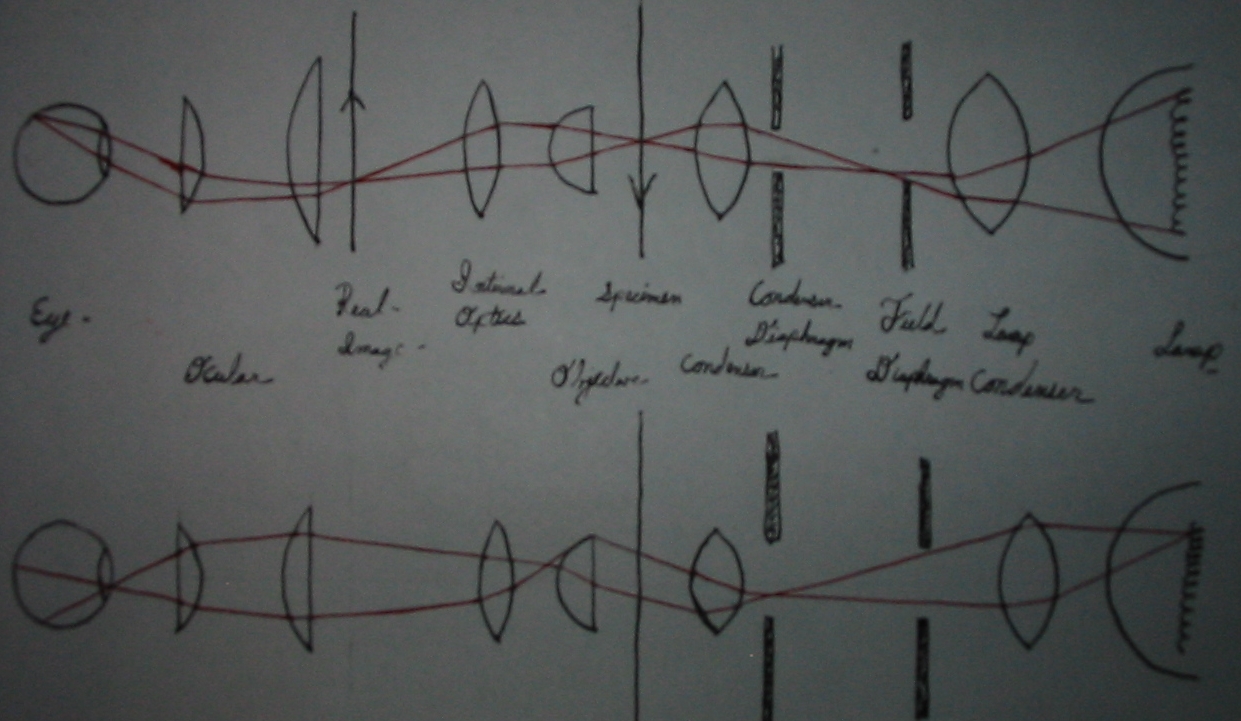
Above: Image forming rays. Below: Illuminating rays.
In the rough sketch above we can see the path of image forming rays, and the path of illuminating rays. For interested parties unused to the conventions of ray diagrams∗, it will suffice to say that where the rays intersect an image is formed. Looking specifically to the image forming rays of each diagram we can see where an image of the light source is formed: at the diaphragm of the lamp, at the diaphragm of the substage condenser, at the rear focal place (rear lens) of the objective, and within the lens of the observers eye. One will also note that as the image of the lamp is formed at the same location as a diaphragm, that diaphram will likewise be in focus with the light source image. For this reason when set up for Köhler illumination we should be able to observe an image of the light source on the substage diaphragm and an image of the substage diaphragm together with that of the light source at the back lens of the objective†. We also can see that an image of the lamps diaphragm will be formed at the image plane of the specimen, and again where it will be magnified further by the eyepiece. For this reason, when focused on the specimen, we should be able to stop down the lamps diaphragm and see the edges of it in focus with the specimen.
If a moment is taken to observe the eye in each part of the above image two important things can be observed; even if not readily apparent in the crude diagram. The path of the image forming rays shows that an image of the specimen converges on the fovea, while the image of the light source does not. Looking to the portion of the eye that is filled by the light forming rays, it is seen that an image of the light source is formed at the iris, and the rays diverge across the retina.
Köhler Illumination
Before getting into the set up process a few important notes are necessary. A filament image is apt to be extremely brilliant, take care to lower the intensity of the light appropriately‡. Do not fall into the misconception that light sources equipped with a permanent ground glass filter or opal bulb are not able to provide Köhler illumination. It will just be very difficult to determine if the light source is in focus on the field diaphragm of the lamp and substage diaphragm. This difficulty may generally be overcome by the introduction of a disturbance (a pencil mark or foil point) on the bulb or ground glass.
- Arrange the bulb of the illuminator in conjunction with the condenser system of the lamp so that an image of the light source is in focus in the plane of the illuminators condenser. Adjustments depend on those available with the illuminator itself, but determining focus is generally a simply matter of introducing a ground glass or scrap of paper at the diaphragm opening.
- Open the lamps field diaphragm and stop down the diaphragm of the substage condenser.
- Position the illuminator so that an image of the light source (generally the lamp filament) may be seen in focus on the surface of the microscopes substage condenser. If set up for horizontal use it is exceedingly simple. When working vertically or at a comfortable incline it seems very difficult until, one takes a small mirror and positions it to view the substage diaphragm easily when standing ready at the microscope.
- Open the substage diaphragm and focus a well stained smear or thin section of uniform thickness on the stage using a 16mm objective and 10x eyepiece.
- Adjust the field diaphragm of the illuminator until it is seen in the field of view had at the microscopes eyepiece.
- Adjust the substage up or down until the field diaphragm is seen in focus within the image plane of the specimen.
- Open the field diaphragm of the illuminator until it is no long seen at at the microscopes eyepiece.
- Remove the microscopes eyepiece and sight down the body tube from a distance of ten inches (250mm).
- Adjust the substage condenser diaphragm until the brightly lit back lens of the objective is just seen to be obscured.
- Replace the eyepiece.
- Repeat steps 5-10 whenever the objective is changed.
It’s worth noting that when sighting down the body tube for step 8 one should be able to see a clear image of the light source. One should also be able to image the field diaphragm and substage diaphragm, which makes this step a wonderful time to stop and center the illuminator and substage condenser. At step 9 it may be necessary to obscure more or less of the back lens to provide for optimal contrast; from 25-33% is the recommended amount which should be obscured. Every increase in contrast beyond that which allows for the microscopist to better discern detail is still an theoretical decrease in numerical aperture and should be avoided if increased contrast is not revealing additional detail.
Examples
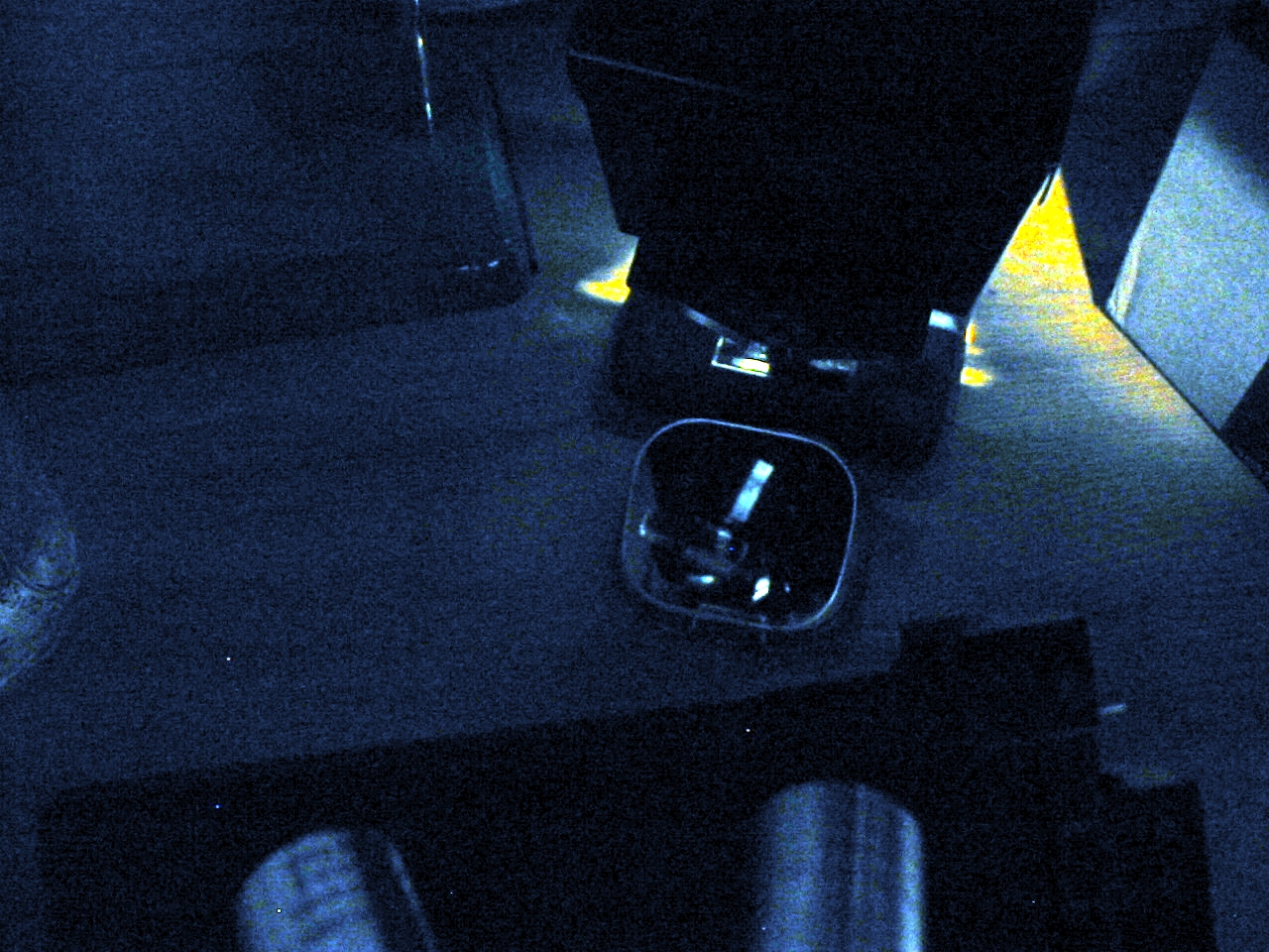
Filament image as seen in mirror.
In the photograph at left, the arrangement of a small mirror for observing the filament image as projected onto the underside of the substage condenser may be seen. In order to better illustrate the situation a bulb with a single long coiled filament was used. For microscopy it is often better to use a bulb with multiple filaments (or an opal bulb or diffuser) so that the entire underside of the substage diaphragm may be filled with light; doing so will result in a more uniformly lit field.

Field diaphragm of the illuminator
At right the image of the the very constricted field diaphragm may be seen. In practice it will not be necessary to stop down the diaphragm to such an extent. The color fringes seen around the diaphragm opening are evidence of the fact the the microscope condenser is of the chromatic (Abbe) type. The fact that the color fringe is of different colors on the left and right sides is proof that the illumination is not entirely axial. For critical work it would be advisable to take the time to properly align both the filament to the lamps condenser and the mirror to the same so that the color fringes are concentric to each other.
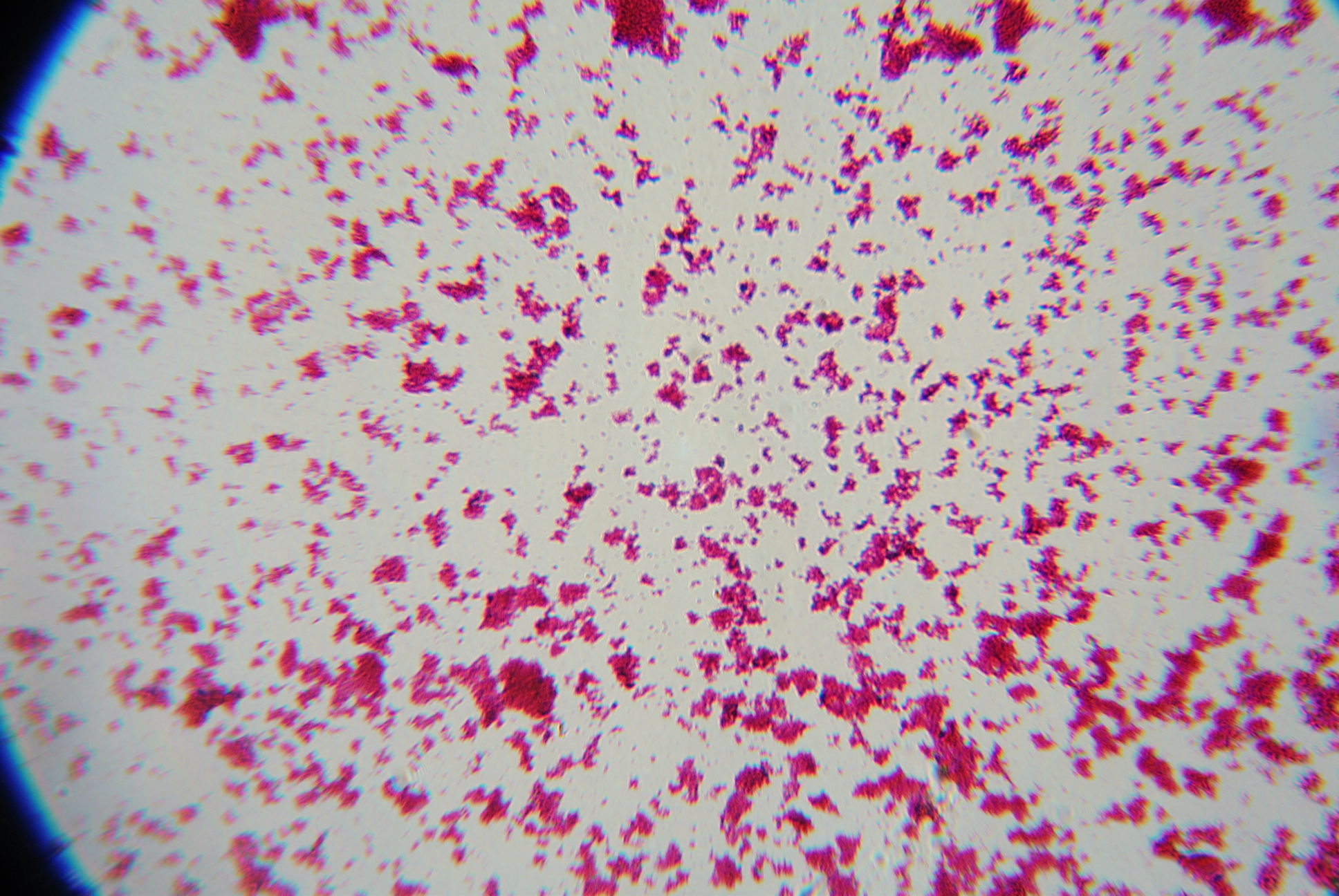
Escherichia coli with 16mm objective and 10x ocular.
In the above photomicrograph we see that although the use of a single coil filament bulb produces a bright image, it is not uniform. Note in particular the right margin of the image where the coils of the filament are most apparent. Despite the limited size of the single coil filament, and the large field of view provided by the 16mm objective, it is worth pointing out that the central portion of the image is well lit by the commonly available bulb. There is no need to rush out and buy an expensive specialty bulb.
Notes:
∗Most introductory courses in physics will cover the basics of ray diagrams as they relate to the use of mirrors and lenses. A simple web search will provide ample explanations and illustrations.
†It can be difficult for some people to view the rear lens of the objective unassisted. To provide assistance one can purchase or construct a phase telescope (Bertrand lens) that is used to align a phase contrast apparatus and sight the rear of the objective with that.
‡When it is not possible to dim the light with the apparatus itself or appropriate filters one may often simply place a plug in dimmer switch between the wall socket and the illuminator without ill effect. Color temperature will be affected but, that is infinitely preferable to damaged vision
