Just a little something a fair number of microscopists do not realize, or give much thought if they do. -K
For many, equivalent focus is nothing more than a little marking on their objectives or nosepiece. Modern objectives are apt to be marked with all manner of things, most commonly it will include the following: the manufacturer, a serial or part number, the power, the numerical aperture, and the equivalent focus in millimeters. Less commonly an objective might also be marked with patent dates or numbers, the immersion medium (if any), the variety of lens system∗, the proper tube length, specialty symbols for infinity correction, colors designating various powers, intended coverglass, marking for correction collars, even zoom or variable focus markings. Most of the markings are self explanatory, but equivalent focus can be a bit confusing.
When working with antique or vintage gear the equivalent focus (hereafter abbreviated EF) may be even more complicated, and more useful. The farther back one goes the more likely one is to find less explicit information marked on ones objectives. Sometimes the only information will be the manufacturer and the EF, if one’s particularly lucky the tube length will be marked as well.

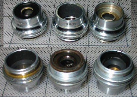
None of these objectives are marked with their explicit magnification.
In the above photo one can see a variety of objectives. At the far left is an old system objective marked 2/3 0.25N.A. 160 Tube Length, comparatively explicit as we shall see and oddly mixing metric tube length with a fractional inch EF. That to it’s immediate right is marked only with its EF, 32mm. Beside that is one marked 4mm 0.85 215mm T.L. its neighbor is the same in all respects but for a 165mm tube length. Next is an 8mm 0.50 N.A. for 215mm T.L and finally a 1.9mm 1.32N.A. fluorite for 215mm tube length.
What is Equivalent Focus?
The equivalent focus is a means of expressing the power of an optical system. Instead of expressing that directly as a diopter measurement, or explicitly as the diameters of magnification†, it is provided as it relates to the focus of a simple lens at a distance of ten inches. This seems an odd way to describe the magnification of any optical system, until one recalls that the microscope is built around the natural relaxed focus of the human eye; ten inches. It seems even more odd now that the metric system has been universally adopted by microscope manufacturers, and microscopes are no longer physically ten inches in length.
Determining Magnification from Equivalent Focus
For quite a long time the older system of measure was used extensively and objectives would be marked with a focal length expressed in fractional inches. When the microscope used a tube length of 10 inches the mathematical determination of magnification from EF was very simple.
Tube length / fractional EF = magnifying power
One may determine the power of a 1 inch EF objective immediately because at ten inches it provides a magnification of 10X. A 1/2 inch objective then provides a magnification of 20X, a 2/3 inch objective provides 15X, 1/6 inch provides 60X, and so on. Relatively simple, and although less direct than marking an objective with the power itself, fractional inches are easy to convert to magnifying power. When the 160mm tube length became common, if not standard, fractional EF was still used and manufactures simply modified the actual power of the eyepieces‡ to provide the marked magnification.
After metric measurements became standard§ the equivalent focus could still be used to quickly determine the magnifying power. Using the above equation one could simply substitute the metric tube length for the metric EF. A 25mm EF objective intended for a 250mm tube length would provide a power of 10X. A 16mm objective for a 160mm tube length system also provided a magnification of 10x.
Things Get Complicated
One with any experience with microscopes is apt to immediately find that their objectives do not bear out the above equations when using other metric EF’s. A common B&L objective marked 4mm might also be marked 43X rather than the 40X one would expect. Is one to believe then that the objective is intended for a 172mm tube length? Absolutely not, rather one should recognize that the powers marked on objectives and the EF is intended as a general designation and not a rigid designation as it is generally taken.
One finds objective marked with two designations of power that are only generally equivalent to each other. The situation prompted one respected authority‖ to write “The engraving of E.F. in terms of millimeters is a stupidity that should never have originated, let alone be used by American manufacturers.” This position is understandable because so many objectives may be found to provide levels of magnification quite at odds with those marked.
In General
If one needs to know the relative power of any objective it’s simple enough to consider the EF and understand that the longer the EF the lower the power, and the shorter the EF the higher the power. It’s common for objectives to be marked with both their explicit power and their EF however, as power diminishes the barrel of the objective becomes physically shorter and there is less room for markings of any sort. It is not uncommon then for quite low power objectives to be marked with the power only as expressed by EF.
Most every objective having an EF of 30mm or greater will not bear an explicit marking of its magnifying power. Objectives of from 48mm to 2mm EF are commonly available for use with compound microscopes. For most uses the following list may be used to estimate the magnifying power from the EF:
 2mm EF provides 90X
 3mm EF provides 60X
 4mm EF provides 45X
 8mm EF provides 20X
16mm EF provides 10X
30mm EF provides 3.5X
48mm EF provides 2X
Notes:
∗This could mean anything from marking the lens as an achromat, flat-field, apochromat, fluorite, strain free, phase, polarizing, or nearly anything else. There are all manner of specialty arrangements and they are frequently marked. Somewhat vexingly, vintage and antique lens are often lacking as to this information leaving one to track it down in old catalogs and promotional papers.
†The familiar times linear or diameters of magnification can often prove complex in historical papers as it was occasionally used to refer to a square rather than a linear measure. Here it is meant to be accepted as the modern form 10X providing a magnification sufficient to magnify a 1µm long object to 10µm.
‡Dr. Gage writes in the seventeenth edition of his encyclopedic monograph The Microscope that the reduction of power caused by using objectives at a 160mm tube length was made up for by rating oculars below their actual power so that the magnification marked on the objective and ocular would provide the actual magnification of the system only when multiplied. He goes on to credit the Spencer lens Company of Buffalo, New York with beginning the trend in 1901-2 of marking both objective and ocular with an accurate measure of their power in addition to their equivalent focus.
§Standard didn’t always mean practical. It wasn’t uncommon for individual workers and laboratories to work in one system of measurement and then convert it to metric for publication. If one ever references a historic paper and finds it littered with strange metric units seemingly chosen for no reason, converting them to imperial units, English units, or United States customary units can often prove amusing. Don’t judge the authors too harshly though, equipment using the metric system was often a hard to justify expense when the old gear still worked.
‖That authority is Dr. Peter Gray. His works on microscopy and microtechnique are invaluable to the beginner and skilled microscopist alike. Oddly enough, his method of determining the power of an objective from its metric EF is to convert from millimeters into fractional inches then calculate; rather than work in millimeters and divide the tube length by EF. All the more odd for the fact that his most significant works were published more than twenty years after the work of Dr. Gage referenced above.