Amateur Photomicrography IV

The setup for photomicrography can seem complicated. In fact it’s quite simple, and one already knows everything involved; provided of course there is some familiarity with the visual use of a microscope. Visually one need only place an object on the stage, direct the illumination of the light source, rough focus based on the objectives working distance, and move ones eye to the eye-point of the ocular. That done, adjust for fine focus and enjoy.

With photomicrography a camera is substituted for the eye. If the camera happens to have the precise optical characteristics of the operators eye then fine focus may be obtained visually and translate without adjustment to the camera. Otherwise the focus can obtained by some other component that duplicates the characteristics of the camera. In theory it’s simple. In practice—particularly if time has not permitted the fabrication of a coupler—switching from the focusing tube of the Kodak No.0 photomicrographic outfit to the camera is a recipe for vignetted images. Wouldn’t it be nice if the camera itself could serve for both focusing and photographing?

It absolutely can and it’s now the only method this technician would recommend if not using an integrated camera system!

Permit me now a lengthy aside not at all written in my usual, tedious, arms-length style. I had never before considered using sheet film in a box camera, honestly, never! Reading through the B&L Amateur Photomicrography manual I saw the words “use cut film” and about lost my mind. Cut film! It’s so obvious! I’m not a skilled photographer and as such am not prolific—more’s the pity I’ll take forever to get any good. As such I might go weeks before shooting the last of even an 8 frame roll of 127, and even longer as I stress way too much over exposure and generally end up with endlessly bracketed frames. But with sheet film! NO WORRIES! 

It turns out sheet film is expensive, a dollar or more for B&W 2-1/4 x 3-1/4, Well, buy 4×5 and cut it down in pitch black! IN PITCH BLACK?! No thank you, I’m enough of a klutz with the lights on. But wait, X-Ray film is orthochromatic? X-Ray film is $20.00 for a pack of 100 5×7 sheets?! A single sheet will cut down to 4 of the slightly less than 2-1/4 x 3-1/4 frames that will fit in Kodak No.0 which means I get sheets of film I can work with under red light for $0.05 a frame! So, yeah, I’m all over that!

Using orthochromatic film would have been easy in the time when the B&L Amateur Photomicrographic outfit was new, today it’s a bit of a wait to obtain film as it will nearly always need to be ordered from a medical X-Ray supplier. With film in hand and all in a changing bag or darkroom remove a single sheet to be sacrificed. Use that sheet to trace out the size of a frame which will just fill the film plane of the camera, and cut it out carefully. Once the size is perfect a method of safely cutting down the film under a dim safelight will be needed. To that end obtain a guillotine paper cutter. Lay the cut down sheet on the cutter and align the long edge with the blade. Then put down a length of white (or otherwise highly contrasting) tape aligning that with the edge of the film farthest from the blade. Repeat lower down from the taped guide for the short edge. By this means a full size sheet may be speedily cut down to precise dimensions in the dim safelight (or total dark if sufficient care be taken).

UNADJUSTEDNONRAW_thumb_47a

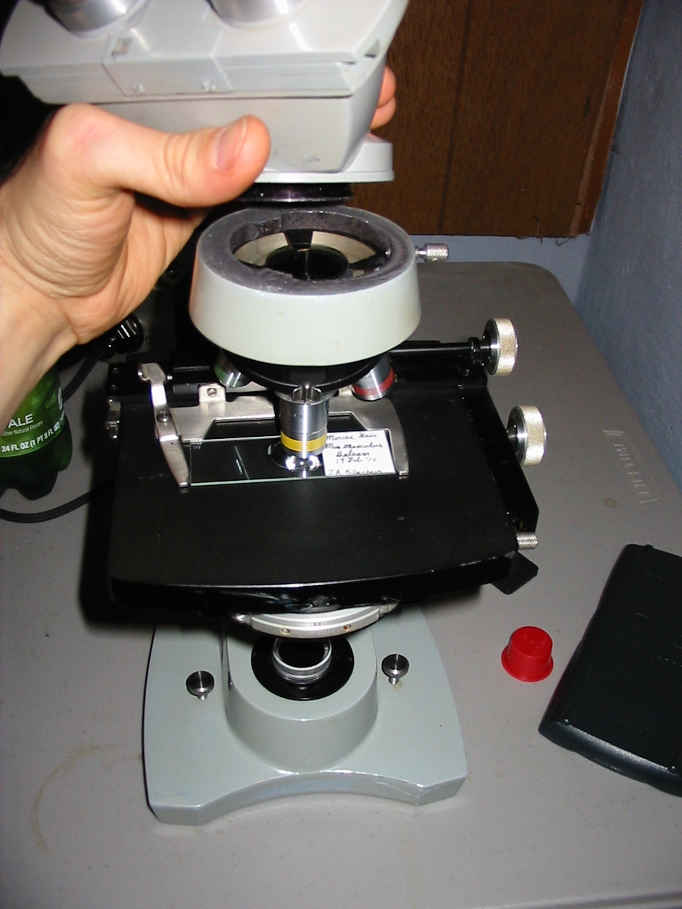
Model R arranged for photomicrography

In a dark room (for simplicity) one should arrange the microscope so it be secure (rubber bands wrapped about the foot will give the Model R a firm grip). Further bands may be used to secure it to the base of a ring stand if one be employed. The arrangement shown at left illustrates the method described. For illumination any handy source may be employed, though it is advisable to use as a source something well baffled which will not permit stray light to fill the working area. Stray light is less a concern when working with roll film but for use with cut film it should be well avoided if at all possible.

Working in subdued lighting one may open the rear of the camera and use a sheet of cut (but exposed to room-light and undeveloped) film as a focusing screen with the shutter held open. Place the film in the back of the camera and carefully arrange the camera over the eye-piece. Turn on the illuminator and make adjustments as required for alignment of the whole apparatus.

When all is well positioned turn out the room light and illuminator. If working with orthochromatic film one may turn on a safelight. Place a sheet of unexposed cut film into the camera, taking care not to move at all the camera or focus of the microscope. Turn on the illuminator and trip the shutter of the camera. Working as just described will likely result in blurry images due to camera shake. Rather than more securely arranging all the elements one may simply leave the cameras shutter open and control exposure by turning on or off the illuminator or placing an opaque card into the light-path.

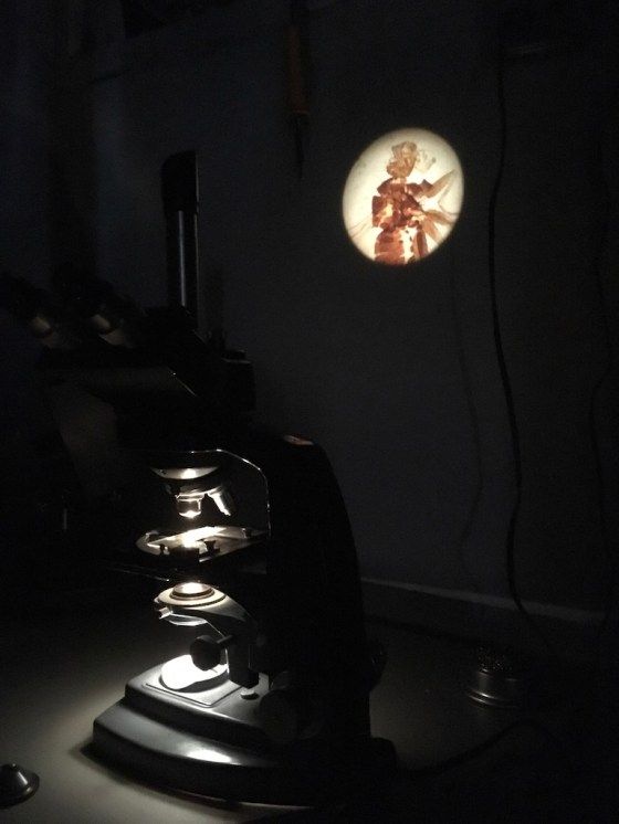
The images above were enlarged onto Fomalux silver-bromide enlarging paper from X-Ray film negatives which were exposed using the Kodak No.0 Amateur Photomicrographic apparatus and Model R microscope from B&L. The issues seen in the thin section (lack of uniformity in lighting) is from a processing defect (uneven development) and is present in the negative. In all of the above images the obstruction of  illumination was used in place of the cameras shutter and the front element of the microscope objective on the Model R was removed.

The resolution of the diatoms in the image at left is far better than one could have expected from a “toy” microscope. No doubt the impeccable condition of the Model R contributed significantly. It’s worth noting as well that without a meniscus lens (as would normally be found in a Kodak No.0) only the Model R’s well-engineered optics were able to affect the image. One is certain to find significant loss of resolution if working with a Kodak No.0 (or other box camera) that has a meniscus lens.

Prism Projection

I’ve written a bit about the DynaZoom and DynOptic before, I’m almost sure I have, but today I thought a bit about where the stand really shines; teaching.

DynaZoom & DynOptic in the Classroom

The stands of the Dyn* generation aren’t my favorite, the fixed inclination is just something I never understood, even in the BalPlan it’s irksome. There is, however, one thing to which the Dyn* line is particularly well suited and that’s instruction. Simpler U or bird-foot stands have a tendency to be roughly handled by students, and particularly in the case when used with a mirror in the light-path will almost certainly never been in alignment, not so with any of the Dyn*’s. The heavy base sits still and because the illumination is integral (unless used with the rather rare-mirror base) will remain aligned provided it is properly set up once.

They’re also great in that of the various optical heads, the photomicrographic tribute-nocular is enormously common. Although it was available with any number of camera bodies, 4×5, Type 80 Land Camera, Polaroid pack film, even now 35mm remains the most often seen. The comparatively (these days) outdated film cameras provide an excellent jumping off point for someone wishing to adapt a digital camera to the microscope. One could still stumble upon the somewhat rare B&L C-Mount video camera tube and teach a class with a single microscope if one had a mind to. But the right angle prism eye-piece is more common, and can be applied to other stands as well.

The Prism Eyepiece

B&L, perhaps more than any other microscope manufacturer had accessories. There was seemingly a device for every need to be had and at least here, outside of Rochester, New York, many of them still turn up on the yard-sale and thrift-store circuit. The B&L prism eyepiece is one many a microscopist would do well to pick up.

UNADJUSTEDNONRAW_thumb_2bc

B&L right angle prism eyepiece

It’s a simple two-part thing, black enamel body bearing a right angle prism in an adjustable mount (the angle of movement is only 10 degrees or so), and a friction fit collar for the eyepiece tube. The collar pulls out from the body and slides easily over most standard 1/16th wall eyepiece tubes where a tiny knurled set screw secures it to the tube. With that in place an eyepiece is installed as normal and the body of the prism eyepiece slipped onto the collar over that. Anyone with more than the most limited experience with B&L illuminators will have noticed that most light sources they made provided a range of illumination that may be described on a scale of too-bright to I’m suddenly blind.

Obviously most illuminators they made we’re meant to be used with skylight or neutral density filters even on their lowest power for visual work. With the prism eyepiece it will be clear just why they provided such ample light.

Demonstration

There’s a lot to be said for the utility of gazing up from the eyepieces for a large and clear view projected upon a wall or screen. Even excluding pains in the neck, it can be Wonderfull for taking notes, or even simply for giving the eyes a bit of a rest, the projection set up for some distance can be a nice way to exercise the focus of ones eyes while not interrupting the use of the microscope.

UNADJUSTEDNONRAW_thumb_2b7

Distance to wall, some 27 inches

Large Format Photomicrography part: IV

The earlier posts of this series have covered everything up to making the exposure, and took a bit of a detour to outline a method for performing the work with an improvised camera. At this point one is expected to have a focusing screen, a loaded 4×5 film holder, and an attachment or integrated camera compatible with the same. Two additional items that will prove helpful but are not strictly necessary are a simple hand-lens (a linen tester or tripod magnifier is ideal), and a photographic light meter. I understand that there are smartphone apps that can serve as a light meter, but I have no recommendations on that front. The remainder of this installment will take the form of a checklist.

  1. Place the focusing screen on the bellows of the integrated or attachment camera.
  2. Properly align the illumination source, the brightest available is ideal but depending on the ideal color temperature for the film non-standard sources may be preferable to those used for normal visual work.
  3. Place a specimen on the stage either in the object holder of a mechanical stage or beneath the stage clips (even if neither are usually employed).
  4. Where available make use of voltage control or dimmer to moderate the lighting to a comfortable level for visual work. Neutral density filters may be employed where the lamp may not be otherwise moderated.
  5. Obtain clear visual focus at the ocular.
  6. Where required (as in the photomicrographic BalPlan head) divert the light path from the ocular into the path of the attachment or integrated camera.
  7. Remove any neutral density filters in use or turn up the dimmer to provide the color temperature dictated by the film.
  8. Where available set the shutter speed to “T” and activate the release to illuminate the cameras light path. If “T” is not present but “B” is employ a locking shutter release.
  9. Where available (as in the Integrated Camera System II) focus the image projected on the ground glass using the control on the camera body. If the image will not focus (as is likely if using an improvised camera) one will need to adjust the length of the draw-tube or camera bellows to achieve focus. Do not focus the image on the screen by operating the focusing mechanism of the microscope-doing so will exaggerate any optical defects present.
  10. Use a hand lens to view the image seen in a clear area of the focusing screen to achieve fine focus without the interference of the grain of the focusing screen.
  11. If available place a light meter over the center of the focusing screen and using the reading calculate the necessary exposure.
  12. Close the shutter mechanism and set the shutter speed founding the preceding step. If using an improvised system without a shutter place a light opaque filter (i.e. tin foil) in the path of the illuminator.
  13. Remove the focusing screen and replace with a loaded film holder.
  14. Remove the dark slide from the holder.
  15. Operate the shutter to make the exposure.
  16. Replace the dark slide.
  17. Note the settings that were used to make the exposure if known. The voltage of the illuminator, color temperature, light meter reading, setting of the cameras control, and shutter speed are of particular usefulness. One should of course note the slides catalogue number, the objective, and ocular (if using one in the cameras light path), used.

B&L Photomicrographic Apparatus VI: AX-1

The final development, before the microscope camera went from still-chemical photography to motion/still digital photography is equal parts groundbreaking and re-purposing. Like the System II the new version maintained the same basic layout and universality, it was made compatible with all the camera backs of the System II. It retained the focusing knob (to date all those known are marked at 3x, 5x, 7.5x, and 10x) but departed from the consumer camera style shutter speed selector and remote shutter release; the new camera was automated.

Since the earliest days of photomicrography it was just assumed the the microscopist would be the darkroom technician as well. Those seeking to record images of their work were expected to practice and understand the skills needed not only for obtaining a clear, useful image at the eyepiece, but at the imaging surface of their camera, and final media as well. Books from the golden age are filled with detailed information on how to properly compose and sequentially expose test images. Entire chapters in books on general microscopy are devoted to the proper taking of photomicrographs. In detailed texts on photomicrography extensive chapters describe the best way to salvage (and in future avoid) over or under-exposed films. The AX-1 changed all that.


For a generation that grew up (or like the author, grew complacent) with the automatic exposure and aperture cameras of the “Kodak Moment” era, the AX-1 no doubt seems unduly complex. A two variable analog meter, no less than six buttons-two thirds of which light, two additional indicator lights, four tumbler set values, all run off of a grounded AC plug in a package the size of a lunch box and weight of a bag of sugar is understandably daunting. The space-hogging controller is only half the unit and like it’s counterpart is entirely useless without the automatic shutter assembly camera. As previously mentioned it is superficially like the System II but in place of a release bears a nine pin cable and connector that conducts light data from its integrated sensor to the control box and carries the exposure signals back. A small electromagnet actuates the simple shutter, and the photo-sensor is positioned to one side of a right angle partially silvered reflector.

To allow for the proper calculation of required exposure one must set a few parameters on the controller before beginning. Film speed is dialed in using A.S.A. units and it’s worth noting that the controller uses the 1960 revision (from what I can tell in use, I’ve not been able to locate anything in the documentation). One must also select the desired reciprocity, which is best left set to “OFF” for most uses. Setting the level of magnification to the nearest value marked on the shutter informs the photo-sensor of the general range of light intensity and is vital for achieving accurate exposure times and light levels. One may also set the desired exposure to a fixed value darker or lighter than the calculated exposure which may be useful for those who want to avoid pushing or pulling during processing.

Once properly set up the user is ready to set the focus of the shutter assembly, load film, power up and begin taking pictures at the push of a button! Imagine, no need to shoot and develop costly trial exposures or to calculate required shutter speeds/exposure times by hand with based on light meter readings. The device can serve as a light meter only and exposure may be done manually at the press of a button. The controller can be put on a separate table and the only source of vibration limited to the movement of the shutter itself. That’s probably the chief point in the AX-1’s favor these days, but it may still be worth while for those more willing to give it the space than to learn about shutter speeds.

-K

B&L Photomicrographic Apparatus V: System II

A Re-design

The System II represents a fundamental change in B&L integrated photomicrographic cameras. Sleeker than the early DynaZoom camera but far more substantial than the later versions, the System II is a step back to the design principles that required a focusing system. It was necessary for the System II to feature a focusing lens system because the unit was intended to be a new universal device for all (camera ready) professional B&L lines, including the earlier DynaZoom/DynOptic lines. Despite maintaining the compatibility of the system with earlier stands, once more the camera backs required are not compatible with previous versions (although they do come in all previous formats).

New Features

The opticians behind the System II seemingly asked themselves ‘how can we make this the last camera a microscopist will need?’ and set about answering it. The systems chief major departure is the coupler, specifically its diameter. At 7/8ths it’s a full quarter inch larger than the previous model DynaZoom camera, and a return to the large size used with focusing DynaZoom cameras. Care was also taken in the design of the coupler, it was made to be removed and a number of versions of the coupler were made, some making allowance for the use of a manual exposure meter.

Once more the camera back attachment point was redesigned. The new male dovetail fitting was made a bit smaller than those used previously and unlike previous models did not feature an alignment screw that required the female dovetail camera back be fixed in relation to the camera. Additionally, where earlier camera backs used two thumb screws the new versions used only one; making it a simple thing to orient the photosensitive surface however one wished without being forced to suffer an inconvenient shutter release or winder position.

Couplers and Camera Backs

Three couplers are known of: the silver Bal-Coated male dovetail, the black lens-less male dovetail, and the eyepiece mount. The silver dovetail makes good use of a Bal-Coated lens to eliminate errant reflection which can prove frustrating with uncoated optics and both it and the black dovetail carry a small slot in the dovetail that mates with the camera. This slot may be turned to align with a similar slot in the System II or turned so as to exclude all light. The purpose of the slot is to permit the insertion of the B&L Cat. # 421240 exposure meters sensor.

Versions

The versions are discrete rather than explicit, which is to say there is not any particular model number to distinguish them that is official but they are readily identifiable. One sort is focusable from below 3x to over 10x. On these models only four magnifications are marked: 3x, 5x, 7.5x, and 10x. Two versions of this sort are known, one having an all black shutter speed selector and the other having a silver ring. An additional version, and perhaps more desirable (if less common) one has the same range but is marked in one unit increments from 0-25x with every fifth mark being numbered.

Accessories

Apart from the previously mentioned camera backs a number of accessories were produced. Special viewfinder adapter plates and eyepieces were available for the various camera backs. It should be noted that these eyepieces were not the film area viewfinder eyepieces that would show the field that would be covered by various popular film sizes. Extension tubes were also available that would extend the distance between the final lens element of the shutter assembly and the camera back. Tubes were made in 2.5x and 5x lengths were produced and could be used in various combinations where special needs required.

Notes:

∗It should be noted that the connection to the shutter in all cases is a male dovetail and the designation here refers to the connection to the microscope photo-port.

†I’ve seen one in use during the course of a museum visit although I’d be hard pressed to say if it were an actually B&L item or the product of a machinist and a tight budget.

B&L Photomicrographic Apparatus III: Integrated Cameras

Microscope Stand Design

Around the halfway point of the last century (1940 or so) microscope design began to change drastically. Modern manufacturing and engineering, together with the proliferation of compact, bright, electric lamps contributed to an opticians ability to design microscopes which provided a new option for the photomicrographer. Contemporarily advertised as tri-nocoular (but more properly referred to as photomicrographic) microscopes began to become available with specialized camera ports that did not require interchanging a binocular body for a monocular body, or the occupation of a standard eyepiece tube by a cumbersome attachment camera.

At the time this was a considerable advance and as photographic process became more accessible and streamlined so too did the process of making ones microscope ready to capture an image. In many cases a microscope could be used visually as normal and simultaneously outfitted with appropriate apparatus capture images on a variety of media. Ones microscope could stand ready for either photomicrography or visual use and a great many sights that were only previously fleeting could be captured.

Regrettably, while some mechanical aspects such as the Royal Microscopical Society (RMS) thread, or 23.2mm eyepiece have become standard, the same can not be said of photomicrographic apparatus. For obvious reasons apparatus from one manufacture may not be compatible with another. Infuriatingly, apparatus from a given manufacturer may not be immediately compatible with a different line or generation of microscopes.

The Systems

It can be impossibly difficult to find information on the integrated camera systems of Bausch & Lomb, so forgive any inaccuracies and permit the establishment of two broad categories; the DynOptic/DynaZoom (hereafter DynaZoom camera) and the Integrated Camera System II (hereafter System II). Each was available with a range of formats and in a variety of styles with various interchangeable or permanently fixed accessories.

The DynaZoom camera was created specifically for the so named line of microscopes and was available throughout the life of that line. When the black finish stands were replaced by the slate finish models the cameras followed suit but maintained the established standards and are interchangeable with the earlier versions and vice versa.

The System II was in simultaneous production with the DynaZoom but was created so as to be compatible with a wide range of microscope lines and to offer improved options and forward compatibility. While still compatible with both the black and slate DynaZoom microscopes it could also be fitted to StereoZoom, and BalPlan microscopes as well as Bausch & Lomb Bench Metallographs, and inverted microscopes. System II also saw the introduction of automatic shutter control with electronic light metering.

One may immediately identify the camera system because in the DynaZoom cameras of every sort there is no independent magnification (focus) control. System II cameras of every sort feature a vertically oriented magnification (focus) control which may be marked from 0 too 25 or from 3x too 10x.

Sorry for the long silence, computer failure and a new job have eaten up a great deal of my time lately. I promise the next post wont be so far away. -K

B&L Photomicrographic Apparatus II: Attachment Camera

The Attachment Camera

The attachment camera as designed by Bausch & Lomb remained primarily the same over its production life. Changes to the apparatus itself were minor and all components have proven interchangeable if one is faced with assembling a complete working device from multiple units purchased separately for parts. The shutter features the following speed settings: 1/10, 1/25. 1/50, 1/100, 1/200, B, and T, and uses a standard cable release. There is no prism release as may be found on attachment cameras from other manufactures. This is a bit of a trade off, as without the prism release one can not direct 100% of available light to the camera. Fortunately, absence of a prism does eliminate its motion as a source of vibration during exposure. In place of a swing out prism a preferential beam splitter is fitted which directs 85-90% of available light to the camera and from 10-15% to the viewer. Aside from the camera itself (see below) the part most likely to be missing is the ocular sleeve which is a metal collar that slips over the tube of the microscope prior to the fitting of an ocular. The sleeve holds the shutter assembly in alignment with the optical axis of the microscope and holds the beam splitter at the exit pupil of the ocular.

This design requires a vertically oriented microscope tube. If used with a classic style B&L Dynoptic binocular microscope one will need to obtain the interchangeable monocular body. When attached the viewfinder projects horizontally towards a seated microscopist. There are two varieties of viewfinder both projecting significantly from the axis of the microscope so that the microscopist need not lean in uncomfortably when using the camera. Each sort makes use of a ground glass screen which the older version views through a large fixed focus condenser. The newer variety uses a spiral focus condenser that improves the clarity which one obtains to a certain extent, but does require that the user lean in towards the lens for proper viewing. Focus is entirely via the controls of the microscope.

Cameras

The camera bellows and bodies that are available for the unit run the gamut. Most common of the camera attachments is the 35mm camera body. The camera itself is often quite diverse and might be any of a half dozen different models. As of this writing the author has found the following 35mm camera bodies: Argus (stripped down, unknown model), Kodak Pony (without view finder), Kodak ColorSnap (complete with permanent lens mount). There are two lengths of bellows tube for the 35mm camera, one providing a 5x enlargement, the other 10x. Each tube is equipped with a dark slide.

Less common is the 2¼ x 3¼ cut film holder which is not equipped with a dark slide. The fixed enlargement factor metal bellows cone is felt lined internally and is confirmed as compatible with Kodak film holders and plates. There may or may not have been a ground glass focusing screen but considering the standard size of the film holder it is simple enough to obtain one from a third party source. Thankfully, a ground grass screen is not necessary as the film plane is parfocal with the fixed focus ground glass viewer. Film is only infrequently available from a limited number of suppliers but may be desirable if one has access to a dark room and a willingness to cut down more commonly available film stock. It is not compatible with the common 120 roll film Graflex camera backs without modification to the camera back or a homemade light seal.

The 2¼ x 3¼ Polaroid instant film pack camera backs may be found and makes use of the 10 exposure peel apart film now produced by Fuji. Although the images obtained are very nice, and provide an easy introduction to medium format photomicrography, the difficulty of pulling film from the camera (so that the chemistry is applied to the film) will require verification of alignment between exposures. The commonly available backs compatible with Graflex cameras are not compatible with the above described bellows. An additional model permanent camera is fitted to a plastic fixed enlargement factor bellows cone and is not outfitted with a dark slide. Unless one has a Polaroid back that is known to be interchangeable with a Kodak film holder it is advisable to obtain the permanent Polaroid version if one is set upon using that format.

The 4 x 5 camera bellows is infrequently seen but provides the best option for those interested in medium or large format photomicrography. A scaled up version of the 2¼ x 3¼ camera, it is metal and felt lined and like it’s smaller counterpart, also does not have a dark slide. The cone is compatible with 4 x 5 camera backs, of all sorts including cut film, film pack, and plate holders. Off the shelf 120 roll film backs from Graflex are compatible and the ease of using such a system can be an economical way for the beginner to get involved with large and medium format chemical photomicrography. Depending on the winder it may be necessary to remove the metal spring that holds cut film plates in place. Ground glass focusing screens are simple to find or make with a bit of glass and a dab or carborundum grit, but the original screen features a thick rubber frame.

Use

No doubt everyone can picture the attachment camera in use on a classic monocular microscope. In the interest of displaying something one might not have considered, below is an image of the attachment camera (with Polaroid back and spiral focus viewfinder) in service on a Phase Contrast DynaZoom as well as two detail images of the difficult to find ocular sleeve.


Notes:

∗Images in reference works term the apparatus the “Model N” attachment camera but I have not been able to locate the appropriate B&L catalog or manual to confirm the proper name.

†The camera back is slightly too wide and thick. A few minutes with a hobby grinder or similar tool is all that is needed to permanently adapt a roll film back. If one is unwilling to dedicate a camera back, a thick felt gasket may be glued to the back and cut so that it projects slightly into the bellows cone to prevent it from being jostled while in use.

‡The hardest part is cutting the glass to the right size and it isn’t even that hard if one has ever cut glass.

On Photomicrographic Apparatus

Modern Variety

There is a staggering amount of digital photomicrographic equipment. Modern student or college level microscopes outfitted for photomicrography have moved away from the previous standard of the tri-nocular head with detachable camera, and are now frequently found with dedicated integral digital cameras. The downside of such cameras aside from the added initial expense (which may double the cost of a comparable binocular microscope) is the inability to upgrade to a superior camera as advances are made or funds become available, and the software requirements. The upside is the possession of a tailored optical system that (ostensibly) has been designed with a knowledge of the microscopes optical system.

The contemporary alternative is the digital eyepiece camera or the eyepiece relay adapter. Despite the versatility of such things their occupation of an eyepiece may greatly complicate the normal use of the microscope. Such secondary optics might just as easily result in inferior image quality depending on the optical system of the microscope. Various artifacts and aberrations may be unavoidable and not immediately apparent.

Classic Variety

Putting aside the issue of format for a moment, classic photomicrographic equipment falls into the same two broad categories as modern digital photomicrographic gear. The traditional attachment camera was designed for use with monocular microscopes and many binocular microscopes were available with an interchangeable monocular body to be used with the photomicrographic outfit. Such apparatus was generally designed so as to use an ocular which could be varied depending on the objectives employed or magnification desired. Unlike modern equivalents most used a beam splitter to provide a viewing port for focusing, those which did not made use of a ground glass screen which could be interchanged with the film or plate holder.

The second category relied upon specialized microscope viewing heads which were designed with a beam splitter which would send a portion of the light into a photomicrographic camera system. Nearly all lines of microscopes by the major houses were available with photomicrographic heads of different sorts encompassing the solely photomicrographic (without provision for visual use) to the monocular and binocular photomicrographic (trinocular). Such microscopes relied on the use of compatible photomicrographic systems generally provided by the manufacturer.

Hazards

An off-the-shelf microscope equipped for digital photomicrography will undoubtedly function but one risks being tied to an overly simplistic microscope that does not meet the requirements of the microscopist as they grow in their ability. The same might be said of a modern or classic microscope outfitted with a digital camera and an eyepiece adapter, with the added difficulty of uncertainty of the suitability of the system. For modern photomicrographic equipment then the chief hazards is inferior equipment and the easy of excessive digital image modification.

Classic photomicrographic gear is only very infrequently available as a complete system in good working order. Obtaining results that do it justice is often heavily reliant on the ability of the user to locate and properly employ gear which was originally designed for use with a given microscope line. Such efforts are often complicated by the lack of relevant documentation or informed sellers§ who greatly increase the difficulty of locating equipment by selling it under some other designation. Recognizing compatible equipment on sight is inherently difficult. Attachment cameras using chemical photographic formats provide resolution that well exceeds consumer grade digital cameras, but one suffers for the time and expense of development and processing of significant numbers of test photomicrographs while getting the equipment in working order.

Recommendations

One can obtain a perfectly suitable modern microscope and outfit it for digital photomicrography at a reasonable cost, assuming of course the images are not required to be used for serious work. A student microscope designed for entry level photomicrography might easily run $500.00 US and one suitable for college level work could exceed $1000.00 without batting an eye. Regrettably, such microscopes are generally inferior to used professional microscopes of similar cost, but for assurance of capacity one could not be faulted for going that route.

A used professional grade trinocular microscope (such as the B&L DynaZoom, DynOptic, BalPlan, AO Spencer 10, Microstar, or 2/4) from any of the major houses may generally be found for far less than all but the cheapest modern student microscopes. Many microscopists have no interest in chemical photomicrography, however, what is seldom considered is that such microscopes as mentioned above existed at a time when the C-mount video camera was in wide use. After obtaining a trinocular microscope one should endeavor to find the c-mount photo-tube sold by the original manufacturer. This author is personally aware that such tubes exist for Bausch & Lomb and AO Spencer, an is told it is true of Olympus, Ziess, and Nikon as well.

One may just as well go the above route and in place of a difficult to find c-mount tube purchase a widely available Polaroid instant camera system designed for the microscope. Film remains available for the more common formats and one has all the benefits of chemical photography without the need of expensive darkrooms or tedious developing processes.

Notes:

∗As distinct from antique photomicrographic equipment which should be taken to include the bellows outfitted horizontal and vertical cameras.

†Alternatively the microscope head might be equipped with a control which would direct 100% of available light to either the ocular(s) or the photomicrographic outfit.

‡By this is meant the difficulty of using a system that can not be tested before hand—most equipment must be purchased on the internet—and the difficulty of recognizing unforgivable visual artifacts and aberrations as a beginner.

§Most of the authors photomicrographic equipment was obtained from dealers who incorrectly identified it as projection or aerial photography gear.

Simple Polaroid-based Polarizing Apparatus

The Polaroid

One is going to need a quantity of polarizing film (polaroid) for any easily constructed polarizing apparatus. Fortunately, the material is inexpensive and readily available from any number of sources online. When seeking the material for construction one should purchase linear polarizing polaroid rather than the circularly polarizing filters common in photography. Do not hope to luck out with a bargain by purchasing the sort of polarizing film sold for use with LCD screen repair and refurbishment, it will not prove suitable.

The size of the film purchased will vary depending on the sort of apparatus which is planned but in most cases a small piece of five square centimeters (two square inches) is enough. One shouldn’t feel obligated to purchase expensive polaroid whether that expense is attributed to the supposed quality of the film (the perfectness of the polarization) or its thickness or any protective coating. Very often one may have the option to purchase polaroid in varying thickness, and the thicker film is useful for applications that require a large self-supporting filter, but in many cases the thinner product is preferable simply because it is easier to work with.

The Example

Not one to miss out on a potential market, Bausch & Lomb marketed a simple polarizing apparatus for users who did not require (or have the budget for) the more complex prism-based variety. Below is seen an exceedingly simple set composed of polarizing film set into light metal frames. One portion is a 21mm disc and the other is of 32mm, a split ring retainer is included. The concise instructions on the reverse of the box direct the user to install the smaller disc in a standard eyepiece by separating the components of the eyepiece so that the disc may rest upon the eyepiece diaphragm. The eyepiece itself then becomes the analyzer which is in this instance the rotating component. The 32mm disc is sized to be compatible with filters used in most substages and serves as the polarizer.

Simple commercial example of a type anyone can produce.

Simple commercial example of a type anyone can produce.

Right away one can see that an essentially identical set may be produced for just a few dollars. If one is loath to risk the cleanliness of an ocular by separating the components to insert the analyzer, a cap may be fashioned that holds the polaroid and fits above the microscopes eyepiece. It will work in precisely the same fashion and has the advantage of not requiring an ocular be put aside for polarizing work only. Regrettably, one will recognize very quickly that such a set, whether the analyzer is integrated with an ocular or placed over it, will not work effectively on a binocular or trinocular microscope.

Special Considerations

For microscopes equipped with binocular or trinocular heads, one should place the analyzer in a location such that it acts upon the light prior to that light being sent into the eyepiece or photo tubes. Fortunately it is often a simple matter to remove the microscopes head and place the analyzer within. Once the analyzer is positioned one must look to the way in which the polarizer may be accommodated. In most cases it is not advisable to use a 32mm disc placed in the substage filter holder simply because rotating it once positioned is inconvenient. Very often only a small effort need be expended to create a holder that may be placed in the substage to facilitate rotating the polarizer. In any case one should endeavor to arrange polarizer and analyzer so that both may be quickly removed or installed, and one of the two is rotatable.

Improvised polarizer and analyzer in place on AO Spencer microscope

Improvised polarizer and analyzer in place on AO Spencer microscope

In the photograph at right one can see that a simple disk of polarizing film has been placed intermediate to the objective turret and trinocular head of this AO Spencer Microstar microscope to serve as the analyzer. A rotating polarizer has been constructed from a plastic film canister lid and aluminum screw cap, it fits conveniently in the 32mm filter recess of the microscopes integrated illuminator. By virtue of the microscopes construction only one finger screw needs to be loosened to remove the head and place the analyzer. For ease of handling, and so that it may serve double duty the analyzer was cut to a size of 32mm and may be used as the polarizer when placed in the substage filter holder of a monocular microscope. One should note that the polarizer is of a size that no light may pass out of the integrated illuminator that does not pass through the polarizer.

Next time: eye-candy! A few nice photomicrographs of slides with bright-filed and polarized light. -K