Polarized Light Microscopy Apparatus

The Polarizing Prism

Prior to the advent of thin-film polarizing filters one relied upon specially arranged prisms of a substance known as Iceland spar. This transparent calcite (primarily sourced from Iceland) has the peculiar property of acting as a double refracting filter. There is a certain amount of speculation that Iceland spar is in fact the old Norse sun-stone of legend that permitted navigation based upon the position of the sun even in cloudy conditions. In any case, the ability of the mineral to polarize light, together with the fact that it cleaves easily into rhombs renders it uniquely suitable for the creation of a various forms of prism, two sorts of which were common in polarized light microscopy.

Invented in 1928 by William Nicol, the prism so designated is composed of two portions of a single crystal of Iceland spar cut at precise angles with respect to the axis of their polarization and cemented back together. Once reassembled in accordance with Nicol’s design the double refracting crystal becomes a filter which effectively reduces any light entering it to a single ray of polarized light. A Nicol prism is easily identified because either end of it will show parallel faces of 68°. That the active faces are at an angle makes the Nicol prism less suitable for use as an analyzer and it will be most often found in a polarizer.

Unlike the Nicol prims, a Glan-Thompson prism has both of its active faces at right angles to the axis of polarization. This simple fact makes it well suited to use in an optical system when one needs to maximize the amount of light which will pass through it, and minimize the distance at which it may be placed conveniently over an optical lens. The Glan-Thompson prism acts in much the same way as the Nicol prism, it simply permits a greater percentage of polarized light to pass through.

Antique Apparatus

Historically polarized light microscopy was practiced much as it is today; with either a petrographic microscope constructed specifically for that use, or a pair of accessories that adapt a standard light microscope to the task. Although the precise configuration of the apparatus took may have varied, it generally took one of two forms depending upon the placement of the analyzer. In each form a polarizer was mounted in place of, or beneath the microscopes condenser. One sort used an analyzer that screwed into the objective end of the microscope body after the objective or nosepiece and so introduced the Nicol prism into the optical axis. The second form fit over the end of the microscopes draw tube so that the Nicol prism is introduced over the ocular at the eye-point with a subsequent lens that focuses appropriately. In either form one of the elements will rotate, polarizer or analyzer.

In nearly all forms the rotating component will be inscribed with markings designating the degree of rotation from 0 too 360. Occasionally, the manufacturer may not provide precise or complete markings. Very often the polarizer and analyzer were sold together in a case as either on its own would be of only limited use. Below is an example of a representative Bausch & Lomb polarizing apparatus from the era of the Triple Alliance (1907 – November 1915) first in its case and then fitted to a Bausch & Lomb BH8 dating to c. 1919.

Bausch & Lomb polarizer (left) and analyzer (right).

Bausch & Lomb polarizer (left) and analyzer (right).

Polarizing apparatus on period appropriate microscope.

Polarizing apparatus on period appropriate microscope.

The black surface will face towards the underside of the microscopes stage in use.

The black surface will face towards the underside of the microscopes stage in use.

The Polarizer

This example, which carries a Nicol prism of Iceland spar friction fit into a cork, is designed to fit into the substage in place of the microscopes condenser. One will be quick to note that this means one should employ the concave mirror in order to obtain appropriately converging light for illumination. Later varieties of the apparatus constructed along the same lines would feature filters composed of selenite with which one could control the color of the polarized light.  Once fitted the condenser adjustment is wracked upwards to bring the Nicol prism as close to the specimen as possible, in this way ensuring the entire field is filled with polarized light.

When mounting a polarizer of this sort (that does not rotate) one should take notice of the orientation of the polarizing prism when placed in position for use. It may be desirable to orient it such that the axis of polarization is not at an odd angle. However one may simply place the polarizer as is convenient and then orient the analyzer.

The Analyzer

The left portion contains no optical components and is little more than a mounting collar.

The left portion contains no optical components and is little more than a mounting collar.

Here, the analyzer being the rotating component, is more complex. Of two portions, the first is fit over the eye-tube of the microscope prior to the placement of an eyepiece and is held in position by a knurled set screw. Once the base portion of the analyzer is fitted to the microscope an eyepiece is inserted and the top portion friction fit into a recess in the unit. Graduated marking around the top portion (which bears the polarizing prism) range from 1 too 360 and show the relative orientation as it is about the optical axis. Due to the limited size of the prism it is not possible to obtain a complete image of the normal field of view with a prism set in a fixed position. For that reason the eyepiece of the polarizer is adjustable in the manner of a draw tube so that an optimum field of view may be had for a given ocular.

The primary advantages of an analyzer of this type are the ease with which the orientation of the analyzer may be read, and the retention of the tube length. Where an analyzer which screws into the body of the microscope between the objective and body tube will add to the overall length of the body tube, this apparatus will not, enabling the markings on the draw tube to be used as normal for coverglass accommodation or other similar adjustments.

Notes:

∗Some of the technical information concerning various varieties of polarizing prims may be found excellently presented in the following pdf available from SPIE, the international society for optics and photonics: PM200.pdf

Cats Whisker Forceps

A recent brush with greatness (see this excellent chap) inspired me to work on a few opaque, dry-cell, mounts. This of course reminded me that I have always lacked a delicate touch. -K

Delicate Objects

When mounting one is apt to run into all manner of materials, from algae too zea stems there is no limit to what one might encounter. While some of the objects to be mounted are simple to manipulate with droppers, section lifters, or brushes, a few require a forceps to be handled effectively. Unfortunately, some of what one may wish to mount is fragile (part of the reason one will want to protect it with a sturdy mount) and the usual forceps will be sure to result in damage unless one is possessed of the most careful hand. There is, of course, specialized equipment for working with small (right down to the truly microscopic) objects; specialized equipment for working with delicate objects; specialized equipment for working with small delicate objects; and it is nearly all difficult to find and expensive.

The Old Solution

The old solution was a simple modification to the common sort of forceps or needle. It proved such a fine remedy to the problem that few who make use of it are unimpressed. In fact, the solution was so elegant that one can still pay (exorbitant prices; $12.00 is usual) for professional equipment making use of the common (wait for it…) eyelash. When a small and delicate specimen had to be manipulated the workers of old would cement an eyelash, for the finest objects, or cats whisker to the usual needle holder or standard forceps and thereby create a more exacting tool without recourse to more expensive instruments.

As a Probe or Pick

If one must manipulate a small object, perhaps pollen or butterfly scales, a straight eyelash bound to a suitable handle will do nicely. It was once (inappropriately enough) thought that lashes from particular genders or ethnicities were superior and catalogs often boasted about the origin of their offerings as being more gracefully curved or uniformly black. Todays suppliers are rather ambiguous as to the source of their offerings and the eyelashes themselves may be human or otherwise. If one takes any comfortable handle, and cleans of oil with a solvent (alcohol-ether 50% would have been traditional) an eyelash, it may be fixed to that handle by a drop of balsam or a few wraps of thread. Such a tool comes to a very fine point that is surprisingly resilient, easily visible, and not prone to breaking, This last point rather important as any who have wade use to the thread of glass micro-manipulators may attest.

As a Forceps

For a larger object an eyelash may prove insufficient when fixed to the end of a dime-store forceps, and that is where a certain degree of preference comes in. Some historic texts make reference to using the bristles of a pig or hair from the white-tailed deer. For a modern worker those materials may prove difficult to come by. One might instead give their floors a sweep and recover a whisker or two from the family cat. Cutting away the very fine half nearest the tip, set it aside for use as with an eyelash, one should then affix the more robust end to a convenient forceps.

Such a tool at times seems to work wonders, as objects may now be grasped without fear of crushing. In truth one would be hard pressed to hold an object so tightly with such a device as to cause damage. Simultaneously, one may be assured of a sound grip. Considering the price of similarly fine ready-made forceps, the result is better than might be otherwise possible.

Modern Acessories for Vintage Stands

Partial as I am to Bausch & Lomb I’m not one to neglect opportunity when it comes along. -K

One great trouble of the amateur microscopist is that economics often dictate the equipment one works with. This is apt to be a vintage or downright antique microscope and the accessories associated with such a microscope are available only rarely. That rarity does not translate to economy. Naturally, occasions come about when some piece of apparatus might be found inexpensively and in working condition; otherwise one is left with little choice than to make their own accessories, which can be enjoyable but is not always practical.

Recently I came upon an individual who produces a limited range of modern accessories for a number of redly available microscopes from a variety of manufacturers. One of the items is a polarizer and analyzer designed for use with the American Optical 60. Being possessed of one and a bit of disposable income, I purchased the device and it arrived today.

The analyzer appears to be composed of a portion of polarizing film in an aluminum frame. Not in and of itself particularly special but it is very convenient having a nicely mounted bit of film in a frame of just the right size. It is recommended that the analyzer be placed in the body of the microscope below the angled eyepiece tube. Placing the analyzer thusly dispenses with the difficulty of using an eyepiece mounted analyzer, and the tendency of such to be accidentally rotated.

The polarizer is composed of a similar filter, of the sort available for digital cameras, mounted in a specialty holder that fits over the sub-stage lamp. It’s particularly nice that the filter is of a type so easily replaced, for although the analyzer may be left safely within the body of the microscope, the polarizer is apt to become damaged at some point. So long as the housing is in good shape a new polarizing filter may be placed on it at any time. The housing on which the filter is mounted is perfectly constructed to elevate the filter over the profoundly convex lens of the illuminator.

Testing the apparatus shows that it is of suitable quality, better (as well made modern polarizing films are) than the traditional Nicol prisms. Overall it is very nice, worth the expense certainly and gratifying in use, particularly as it has the very tailored feel of being made by one who possesses the exact model for which it has been constructed. I’ve resisted the urge to post pictures and include links, but suffice it to say the set may be found on eBay.

The Camera Lucida

Lets toss this off quick and move on to something else… -K

The camera lucida is a sort of artistic crutch which relies on the dedication of its adherents for its success. To be sure one can enjoy incredible results with the camera lucida, but the requirements of its use coupled with the complexity and expense of the device are sufficient that for casual micrography one is better off with other methods. For the individual with the rigid dedication to acquire skill with the camera lucida it is a tool of wonderful capability, for nearly everyone else it’s a device of torture.

The principle on which the camera lucida operates is reflection. Whereas in the previous post an image of the specimen was reflected onto the drawing surface, here an image of the drawing surface is reflected into the eye as it simultaneously observes the specimen. Apparatus which achieves this has been adapted to all manner of situations and some schools of art teach the use of the camera lucida to artists as a method of perfecting perspective. For micrography the camera lucida seems to have fallen largely by the wayside, perhaps even more so than micrography in general. However, modern camera lucidas are still available and there are occasional adherients in professional and amateur microscopy who make regular use of vintage instruments.

Idealy one wishing to begin serious micrography with the camera lucida should purchase the apparatus. If however one wishes to get an idea of the use before making the expenditure a simple experiment can be made with nothing more than a coverglass. Incline the microscope so that the body is horizontal and position a coverglass at a forty-five degree angle over the eyepoint of the ocular. When aligned correctly and the specimen and area below the coverglass are illuminated just right one will see both when the eye is placed close above the coverglass.

Apparatus of this sort was manufactured for many years which consisted of little more than a coverglass (or neutral tint reflector) in a frame held to a circular fitting which would slip over the rim of the ocular. Professor Abbe improved on this design significantly (others did as well but Abbe’s apparatus is the most generally found) by replacing the simple reflector with a neutral tint reflector having a small hole in its center and cemented between two right angle prisms. Parallel with the plane of the reflector he placed a mirror which would reflect the image of the drawing surface onto the reflector. With the device over the eyepoint of the microscope ocular one could observe drawing surface and specimen as a single image while keeping the microscope inclined in the usual position.

Excepting skill, success with the camera lucida is largely a matter of alignment and lighting. Proper alignment is had by first ensuring that the position of the reflector is in the plane of the oculars eyepoint. If this condition is not met no description of the difficulty and aggravation written here will serve. Next one must position the microscope so that the drawing surface is in plane with the image provided by the eyepiece. In practice this is most easily achieved by keeping the microscope fully vertical and the drawing surface fully horizontal. If this is the case the mirror of the camera lucida may be positioned at a forty-degree angle. If one has a camera lucida with the mirror fixed at an angle other than forty-five degrees the drawing surface will have to be inclined to ensure that a ray of axial light is at a 90 degree angle with the drawing surface.

Once things are aligned lighting must be considered. Light the specimen well enough for clear vision, and the drawing surface well enough that it is not overpowered by the light of the specimen or overpowering of it in turn. The variation of the Abbe camera lucida by Bausch & Lomb pictured below bears a variable series of filters which may be turned into the path of light reflected into the eyepiece to afford some level of moderation. In practice it is often more expedient to simply reserve a variable intensity lamp for illuminating the drawing surface.

The upper portion with filters to limit light sent to the eyepiece reflector.

The upper portion with filters to limit light sent to the eyepiece reflector.

Below one can see that with the microscope fully vertical the mirror may be positioned at forty-five degrees and the drawing surface left horizontal without distortion of the drawing surface. This is not the most comfortable position for use but it is the simplest to set up. Two illuminators are visible in the photograph. That on the left is used exclusively to light the specimen and bears a frosted daylight glass and 0.3 neutral filter. The illuminator on the right is used only for lighting the drawing surface and bears a frosted daylight glass as well. The bulb in each case is a 75watt Mazda halogen spot lamp.

Abbe camera lucida by Bausch & Lomb circa 1920 arranged for use

Abbe camera lucida by Bausch & Lomb circa 1920 arranged for use

Looking into the camera lucida one is presented with an image of the specimen and anything that appears below the mirror. If the image of the drawing surface is too dimly lit it will be impossible to see the image of the pencil point and therefor impossible to trace the outlines of the specimen. One may find that with low powers it is often necessary to dim the light on the specimen and increase the light on the drawing surface. In the case of higher powers one will find the lighting needs reversed. With some varieties of camera lucida one must be certain to keep ones eye in the same position continuously until the micrograph is complete, otherwise the image seems to move about on the paper. With the Abbe camera lucida one may move the eye as the image can only be clearly observed when it is above the hole in the reflector.

Below is something of the image one sees while looking into the camera lucida. At the right one can see a portion of the pencil while to the left one can see the reflection of that pencil simultaneous to the image of the letter “e” slide. The lighter central portion of the image in the eyepiece is not visible in use but is caused by the borders of the hole in the reflector.

Looking into the eyepiece

Looking into the eyepiece

Some time I shall have to make more of my efforts with the camera lucida fit to read of. Maybe put up some of the little things it permits one to do into words, but for now the camera lucida is rather more trouble than it is worth. Without an inclined drawing table it is uncomfortable in use and provides generally inferior results as it does not encourage one to spend any time improving ones skill.

Assisted Freehand

In a sense it’s all just assisted freehand, but I think the meaning is clear. -K

Yesterday efforts were made at getting something on paper and learning a bit on setting up properly. Regrettably those efforts will have accomplished very little of a immediately practical sort. The images produced might be used to visually identify a slide at a glance if its label has fallen off, but that is assuming there are no similar slides on hand. My little sketch could verify that it is of a letter “e” but one would be hard pressed in putting it definitely to a particular unlabeled slide of a letter “e”. Because there was no assistive device that would help with sizing and dimension, we end up only with a general rather than an accurate depiction; one couldn’t use the sketch to measure the size of the letter.

Fortunately, the technique used previously can be rendered very practical by the addition of a simple object that may be purchased for from ten to fifty dollars, or made at home for a good deal less. This device can be used for any number of very usefull tasks from micrography to counting, measuring, or locating. One can use it on essentially any microscope at any magnification and it will last a lifetime. This miraculous device? The humble graticule also erroneously designated the reticle or reticule.

A graticule, the name of which comes from the Latin for gridiron, is nothing more than an optical device on which a ruling of small squares has been marked. This is technically the only accurate description for a graticule as markings composed of either various lines or any grid which is not broken up into even shapes would be a reticule; a micrometer or sighting ocular is a reticule, while a simple counting ocular is a graticule (excluding of course the complex rulings of Neubauer which would be in places reticule or graticule). In practice few people make any distinction between the terms and one is likely to find suitable graticules under various names.

The use of a graticule is quite simple and requires only an eyepiece that contains a diaphragm located at the point in which a real image is formed. In practice this means a negative ocular of the Huygenian type with a field stop between the object lens and the eye lens. At the optical plane of the field stop a real magnified image of the object is formed, which may be observed by placing a circle of tissue paper or frosted glass thereupon. When the graticule (or anything for that matter) is positioned at a point where a real image is formed it will be seen conjugate with the virtual image one observes when looking into the eyelens of the ocular. For more detail concerning real and virtual images one can consult the section on Object-Image Math in Douglas B. Murphy’s excellent book Fundamentals of Light Microscopy and Electronic Imaging.

So, assuming one posses a graticule either purchased or home made and a Huygenian ocular with removable optics, one may fit the graticule to the ocular. Begin in a scrupulously clean and dust free area, as nothing is quite so infuriating as introducing dust to the inside of an ocular, and unscrew the eyelens. With the eyelens removed insert the graticule which should fit just within the tube without force or slop. For standard oculars by Bausch & Lomb and most American makers a graticule with a 21mm diameter is best. In some cases manufacturers provide split rings (as pictured) which will hold the graticule in place so that it will not rattle about even if the ocular be roughly treated. If one is had and the graticule is to be left always in a particular ocular place the split ring before screwing back into position the eyelens of the ocular.

Image

Ocular body, graticule, friction ring, and eyelens, seen in the order to be assembled.

With the majority of graticules the lines are ruled upon one surface or the other and each orientation should be tried. If the rulings are more clearly in focus with the eyelens screwed fully home then that orientation should be selected before one settles for having a loosely fitted eyelens. With the graticule in place in the ocular one should focus a slide upon the stage of the microscope and observing it with the ocular find both the rulings and the specimen sharply defined. If the rulings will not come to focus conjugate with the specimen, the eyelens must be screwed down or up until they are. The eyelens and orientation of the graticule should be manipulated until the rulings are truly conjugate with the image of the specimen. Which is to say they should be neither more or less sharply defined and appear as if on the same level as the object although overlayed.

For drawing with a graticule one would do best to use an ocular of low power and obtain higher magnification with the objective only. The reason for this is well explained by the equations in the above mentioned book but, suffice to say that the area covered by each square of the graticule at a given magnification will be less when that magnification is obtained with a low powered ocular. With the graticule in place one need only use a drawing surface ruled into squares to transfer by hand the view seen through the ocular to paper in the method described yesterday. The rulings will assist in both positioning and consistently representing the size of specimens sketched.

In the above photo one might notice that the graticule pictured has rulings in only the very central portion. At first it might seem as if the ruled area being less than that of the oculars diaphragm would be a great hindrance as the entire field of view would not appear ruled. The reason for using this particular graticule will be obvious when it is noted that it is not used with flat-field objectives. By limiting the area covered by the rulings to the central third of the field of view one insures that spherical aberration of any significance is not depicted in ones micrographs. Images in which optical defects are faithfully represented are of as dubious value as live blood examinations where quacks point to specks of dust or dirt as proof of one malady or another…

Now then, if one knows the spacing of the rule on both the graticule and drawing surface, together with the magnification employed, measurements of a sort may be taken on the drawing using no more specialized apparatus than a ruler. This method of measurement is rather less precise than others (tough quite accurate) but requires neither a micrometer object slide or micrometer eyepiece and serves well for work of all but the most critical sort.

With a graticule in place and ruled paper one may produce micrographs of impeccable quality and enormous size (by moving the slide so that the contents of a square are transported across the field). If one is of limited resources or has in the past attempted other apparatus without good results, no better aid to drawing with the microscope can be had than the graticule. Unlike other apparatus to be covered later no special positioning of the microscope is needed and no great effort is required to become adept. An ocular fitted with a graticule may be dropped into position and used at a moments notice, I commend it to any microscopist.

The Complexity of Basics

It’s a great loss that the enthusiastic often give up for want of ready acumen, when enthusiasm is quite what keeps one going. -K

It’s quite going to put some people out to know there is no getting around having some talent when it comes to producing a micrograph. At its worst its no different than drawing from life, though at the best it may be compared unfavorably to tracing. The are as many tools for assistance as one could want, yet no substitute for that ability that only comes of practice. Very briefly the most common apparatus will be touched upon in this series with special focus on the principles, as they apply regardless of the tools.

The difficulty of drawing is as much a matter of recognizing position and the relationship between objects as it of gaining the mechanical skill that comes of practice. while skill counts, that comes with time; placing things accurately is something one can begin from the very start. This bears mention because many people will come to micrography with the impression that the tools provided for it will permit ready ability in producing a fine illustration. For the most part, all the tools involved provide only the outlines, dimensions, and relative positions of specimens, the detail being filled in by ones eye alone. This may appear a great imposition to some but it is worth remembering that there is a world of difference between the requirements of a micrograph and a photomicrogrpa; subsequently, one should consider ones intent and goal.

While at times a full and detailed sketch is required, more often than not one may wish only to capture a particular area or structure in any detail. Still other times one may need only to make a measurement, which is very quick to do provided preliminary gymnastics are performed ahead of time. Some apparatus requires considerable preparation, more than photomicrography even, so ones intent should align with ones purposes at the outset. While digital photomicrographic apparatus has lately turned imaging into a spur of the moment thing, the old methods simply do not allow it.

Since ones needs may vary it is not unlikely that ones tools should vary as well. Some of the tools will surely prove challenging, and the various sorts of camera lucida though all operating on the same principal, have their own vagaries inherent to their construction. It is important however, to learn well the tools one possesses, there being enough expense and difficulty in the acquiring. The tools may be thrown into a few broad categories:

  1. Those which facilitate free hand drawing.
  2. Those which project an image from the microscope onto a drawing surface.
  3. Those which project an image of the drawing surface onto the plane of the image formed by the microscope.

In the first group one will find any of various graticule’s which divide the field of view so that it may be reproduced on a similarly divided drawing surface. It is not unlike the methods a draftsman would use to produce and enlargement or reduction, or a painter would use in copying a landscape from a photograph with a ruled transparency and canvas. The one pictured below dates to the early 1900’s and has only the very center portioned ruled. Modern equivalents may be had in numerous forms from all major makers. A graticule of this sort is placed onto the diaphragm of an eyepiece (generally Huygenian) and focused by minor movement of the eye lens.

IMG_1222

B&L graticule dating to the early 1900’s

The second group includes any of the various methods of producing a microprojection. Mirrors, prisms, and projection eyepieces may all be placed in this category together with the specialized projection microscopes and old form plate photomicrographic apparatus (used as a camera obscura),  the photographic plate being replaced by a glass and bit of paper. This first photo depicts two forms of projection head by Bausch & Lomb here seen with the microscope horizontal the size of the projection moderated by the distance of the microscope from drawing surface. That on the left consists of a mirrored right angle prism with a few degrees of movement either direction of forty-five. That on the right is a collard mirror which can accommodate any angle and therefore wider angle of drawing surfaces. The second photo shows a Bausch & Lomb model N photomicrographic head with medium format attachment, being just the size for drawing on a 3×5 index card.

It's simple to work up a reflector of this sort from what is on hand.

It’s simple to work up a reflector of this sort from what is on hand.

Any light shield which can be fitted to the microscope and support a glass plate will serve.

Any light shield which can be fitted to the microscope and support a glass plate will serve.

The third group would consist primarily of the various forms of camera lucidas proper, as well as the items operating on the same principle. These are by far the most well known of all the drawing tools and the forms which they take vary wildly. From the Gunrow, and Wollaston’s, to the myriad forms of simple reflector and Abbe camera ludica, the diversity of forms is simply incredible. Abbe’s camera lucida is the most common and frequently available. Shown below are two forms on the Abbe Camera lucida. In the version on the left one is only permitted to incline the drawing surface on a single axis and is limited in its position from the microscope as the reflector is rigidly fixed. The older form on the right permits the mirror to be placed at any angle as well as any distance so that the position of the drawing surface may be made convenient.

A simple and a complex form of Abbe camera lucida

A simple and a complex form of Abbe camera lucida

Brush-up on Brushes

One thing that is somewhat ubiquitous in the microscopy of yesteryear is the camel hair brush. Unlike some items one might find mentioned in the books of Gage, Carpenter, or Allen the camel hair brush seems pretty self explanatory. It lacks the cryptic sound of something like Gold-Size or mystique of a term such as Japan-Black, simply because everyone knows of camels and brushes.

It’s logical to think that a camel hair brush is simply a brush with bristles of camel hair, but that would not be correct. A camel hair brush is nothing more or less than an inexpensive brush with nondescript natural hair bristles. Of course some number of camel hair brushes might actually be made from camel hair, but it’s far more likely to be ox or even horse hair.

Keeping a few camel hair brushes on hand is a good idea. They are a versatile tool when it comes to manipulating small and delicate specimens. A camel hair brush can be had in innumerable sizes and they can be trimmed to any shape one needs with a small pair of shears. Additionally, wide brushes can quickly dust off a microscope or work area, even a delicate lens, far easier (and safer) than a rag or cloth.

When purchasing brushes for use with the microscope it’s important to remember that there is no reason to spend a bundle on fine sable brushes. One must also remember that plastic (often called synthetic) handles or bristles should be avoided at all costs. Many of the solvents and liquids used in microscopy are able to dissolve plastics in just a moment. A set of “watercolor” brushes can often be found at a craft or hobby shop for just a few dollars and is likely to include everything from a very fine tipped brush of just a few bristles to a half inch broad or more “wash” brush.

Artists will often speak about the virtues of fine ferrules and disregard the cheapest brushes out of hand. The only fault of the cheapest natural hair brushes is their tendency to shed hairs. When painting a shed bristle can be disastrous, in microscopy it is only a minor annoyance.

Next time you’re reaching for a fine needle to position a specimen, or pulling out a Kim-Wipe to clean of an ocular, consider giving a camel hair brush a try.

A Dull Return; The Centering Card

After a few weeks of seemingly endless labor, waiting, and paperwork, I’m all moved in to my new home and finally privy to some free time for microscopical pursuits. One of my upcoming efforts requires a very simple apparatus that positively anyone can construct at home, and no maker of permanent mounts should be without: the centering card. When producing a slide one must be mindful not only of the handling of the specimen, but of the appearance of the finished slide as well. An excellent specimen and fine label can go a long way towards providing a professional look, yet the effect may be spoilt by something as simple as an off-center cover-slip.

A centering card is a surprisingly simple device which I first saw illustrated in the pages of Simon Henry Gage’s perennial work The Microscope. The illustration below is taken from the sixteenth edition of that august work.Image

One can see just how simple the thing is and and acknowledge the virtues of a well centered cover-slip yet still fail to appreciate the utility of the centering card, until of course one puts such a card into use. Of all the methods and devices one may use in centering a cover-slip none is quite so straight forward and versatile, so let’s set about producing one.

No very specialized materials are required to construct such a card and one can utilize whatever is on hand. Today I used two 5″x7″ index cards, a pair of shears, some rubber cement, a pencil, a pen (not pictured), a ruler, a 1″x3″ slide (not pictured), and a circle templet by Staedtler (not pictured).

Image

One may of course use far more durable materials than an index card, anything from poster-board to wood or even metal might serve admirably, and I would encourage those so inclined to make use of what they have. For my own part I prefer index card as the entire centering card may be produced so rapidly from them that it is a simple thing to produce one for any particular dimension of slide or cover-slip as the need arises.

After collecting the required supplies one must cut one index card into three pieces as I have already done in the above image. The goal is to produce three specific pieces: one with a long and perfectly straight edge, and two with perfect right-angle corners. Once the cuts are made the first two pieces may be glued to the second (whole) index card. By afixing the first long piece across the bottom of the second card, and one of the right-angle pieces tight against it, a depressed area with a perfect right-angle is produced. It is then a simple mater to position a slide against the edges of those two pieces and glue the third piece to the card so that a three-sided depression exactly fitted to the slide is produced. Tracing a pencil line along the top of the slide and drawing two diagonals with a straight edge pinpoints the center of any slide of the same dimensions placed into the card.

One may now finish the card for whatever size cover-slip one intends to use. For my next effort I will be making use of 18mm circular cover-slips so using a circle templet (though a draftsman’s compass would work as well) I marked the area around the center point accordingly. In the case of square cover-slips it’s a simple thing to position them with the aid of a ruler. Finally I noted on the card the dimensions of the slide, and cover-slip for which it is intended.

Image

The entire operation took only five minutes and produced a functional centering card that will save me the stress of trying to “eyeball” the position of my upcoming mounts. There are of course commercial devices that can serve the purpose of our humble card, and one can often achieve quite good result simple by preparing their mounts over quadrille-ruled paper, but the speed with which one may produce a serviceable centering card specific for slides and covers of any dimension, makes them a must in my book.

On The Hand Lens

The modern three objective (that turret changer is ubiquitous) microscope so common in school rooms, medical offices, and amateur or professional labs around the world may easily contain several dozen individual optical lenses. A common 4mm objective might have as few as three or four optical components. It is not until an effort is made to correct aberration that the number of components starts to climb. A single objective corrected for some chromic aberration and flatness of field (a plan achromat to be technical) may be composed of ten or more lenses. Top of the line super corrected objectives (say one of the infinity corrected apochromatic immersion variety) might contain over a dozen at the low end and rapidly approach twenty optical components or more.

When one works with a device composed of so many precision optical lenses it’s easy for something as humble as the hand lens to seem unimportant, if it is considered at all. Why spare a moment to even think about such a simple and inexpensive magnifier when objectives formerly costing thousands of dollars are becoming more common and accessibly priced every day? The simple answer is of course that one can not always take their optical stand into the field (nor should one). With the recent proliferation of intensely portable field microscopes one might be tempted to forgo the purchase and use of a hand lens entirely, but in the long run it is often a better decision to ignore the flashy field microscopes instead.

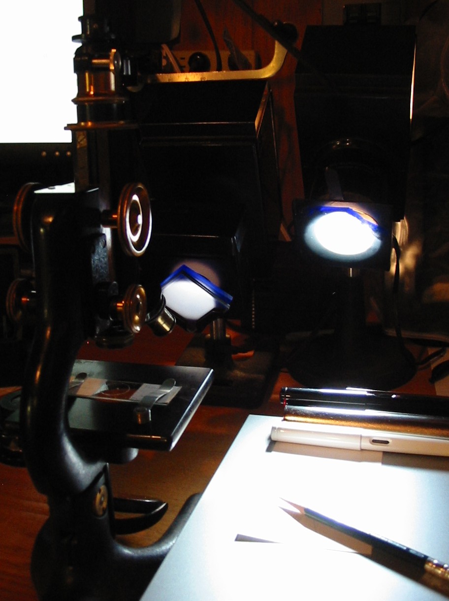
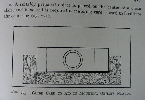
A good hand lens can be as essential a component of a microscopists kit as anything. When identifying a specimen or searching for the best candidate for mounting, the few diameters of magnification provided by a hand lens are often indispensable. Able to be taken to the field with no more specialized equipment than a pocket or a lanyard, a hand lens is eminently portable. With an improvised stand, a hand lens may be pressed into service as a dissecting microscope or a bullseye condenser. It’s easy to see that with a low cost, small size, and myriad of uses, no microscopist should be without one.

Unfortunately for the beginner, it may initially seem as if there are as many configurations and names for the hand lens as their are subjects to view. Should one consider a linen tester, a burning glass, a loupe? What about these other things, I thought Coddington and Hastings were towns in England?

While the appearance of a hand lens may be nearly unlimited, it is absolutely not the case optically. There are only so many ways a lens or series that will fit in a small package can be arranged. Once composed that optical lens (or series) may be fitted into nearly any handle, and that is where the overwhelming variety is rooted. The case or fitting of the lens is determined more by convenience or the intended use of the hand lens than its optics. The heavy brass and glass Sherlock Holmes style reading glass so often pictured when one thinks of a hand lens is no different optically than any of a dozen plastic bodied magnifiers one might pick up from the corner druggists. Well, there is certainly one significant difference, and it will be the first considered.

Glass or Plastic

When considering the choice between a glass or plastic hand lens many people will assume glass to be superior optically and plastic more economical. Eyeglass wearers will immediately see things differently. Few are the optometrists who will not sing the praises of expensive polycarbonate or optical plastic lenses. Throwing around terms like impact resistant, shatter proof, feather-weight, or scratch-free, as if they mean anything is roughly as helpful as describing ones pick-up truck as “Like a Rock.” There will be endless talk about the fragility and weight of glass, how prone it is to scratching,  and whatever else can be said to sell an expensive plastic lens.

The simple fact is that glass is superior optically, period. Naturally, glass can shatter, but that is only because it is so incredibly hard. High quality optical glass may easily rate a seven on the Mohs scale of hardness. Only substances as hard or harder are able to damage the surface of a glass lens, so it’s easy to see why rating a seven on a scale which only goes up to ten is desirable. Glass does tend to be rather heavy though so if you simply must have a very large detective style hand lens with you on every trip to the backyard or pond plastic may be the way to go. However, one must be cautioned that any plastic lens with handled roughly or wiped with a dusty shirt tail will rapidly become a cloudy, scratched mess.

Some high quality plastic hand lenses are available with various special coatings and treatments exactly like the ones they provide for eyeglasses. Such coatings often cause the lenses to cost more than a similar glass lens. A small price tag being in my opinion the chief point in plastics favor, I have never been willing to give it up for an ounce or two of diminished weight. I very much recommend going with glass optics for any hand lens.

The Optics

Now the best part! The optical quality of the various configurations of hand lenses is surprisingly varied, but tend to be of three basic types only; the single biconvex lens, the Coddington magnifier, and the Hastings triplet. Each has points in its favor and drawbacks, times when it shines and times when it’s use is infuriating.

The vast majority are composed of a single simple biconvex lens, generally with a field of view spanning an inch or more. A positive lens (also called a convergent lens) such as this almost never provides a level of magnification of over seven diameters. High levels of magnification require a shorter focal distance and must be held close to the eye. In general anything providing over five diameters will be called a loupe and will be fitted into a housing convenient for placement very close to ones eye. Nevertheless it is not uncommon to see simple magnifiers marketed as providing ten diameters of magnification, and they may but it is of dubious value.

Single lens magnifiers naturally provide the worst quality image (the most optical aberration) but are often the largest when it comes to field of view. When less than five diameters of magnification is needed a simple biconvex hand lens can serve nicely for most purposes. Lower levels of magnification suffer from less aberration and many botanists and etymologists find that a two or three diameter lens with large field of view (providing for a long focal distance) can be just the thing for field work. There’s an enormous variety out there but the majority are simply a bare lens with some sort of handle so care must be taken that the lens is not damaged.

It is also rather common to find multi-lens units which feature a number of simple biconvex ( or rarely plano-convex) lenses which may be slid out of the handle for use, and are protected by the handle otherwise. In units of this type each lens generally provides a different degree of magnification. Multi-lens models of this sort often claim to provide compoundable levels of magnification, each lens singly and then in conjunction. Although multiple biconvex or plano-convex lenses used in conjunction can provided compoundable magnification, I have never seen a hand lens of this sort which provided for the necessary space between the lenses to do so effectively. Do not buy a double lens unit with a two diameter lens and a five diameter lens thinking it will provide ten diameters when using both in conjunction.

When performing non-critical work which requires five diameters of magnification or less single lens unit will do nicely. In some cases the spherical and chromatic aberration of such a lens is unacceptable. Other times, five diameters is simply not enough magnification. A step up in quality (and complexity) from the single biconvex lens is a funny little outfit known as a Coddington magnifier. It’s another single lens outfit but a trick of optics lets it provide a higher level of magnification while stopping back much of the aberration that limits other single lens units to about five diameters of magnification.

In a Coddington magnifier one finds a single biconvex lens of significant thickness. Unlike the simple biconvex lens style discussed above, a Coddington magnifier is often asymmetrical, having one optical surface that is significantly more convex than the other. This asymmetry can be traced back to another type of hand lens known as a Stanhope which is almost never seen today. In any case a Coddington magnifier is able to provide significantly more magnification than other simple biconvex lenses, up to about twenty diameters, because its optical surface is highly convex. As described to this point a Coddington would still provide a high level of aberration, to eliminate this aberration it is removed rather than corrected. A deep grove is cut perpendicular to the optical axis and this equator effectively blocks the more distorted rays of light (those farther from the optical axis) which would have passed through the lens into the eye of the user. Although this feature effectively limits much of the aberration present it also drastically reduces the field of view so that a one inch Coddington magnifier providing five diameters of magnification may only have a field of view of a few sixteenths of an inch. A Coddington will often cost a bit more than a simple two or three lens biconvex unit, but if more than five and no more than fifteen diameters of magnification is needed can be worth it. It’s not uncommon to see Coddington magnifiers boasting magnification of twenty or even thirty diameters but due to the nature of the lens it’s really not worth exceeding ten diameters when purchasing a Coddington.

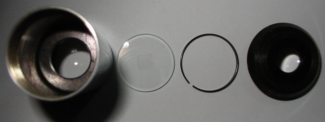
The other common option is the Hastings magnifier, also called the Hastings triplet. As the name suggests this is a series of three lenses (two convexo-concave lenses and one biconvex lens) cemented into a single optical unit. Rather than stop out aberration as in a Coddington, a Hastings magnifier corrects for most spherical and some chromatic aberration, producing a very flat, bright, field or view. This means that a Hastings magnifier is able to provide a much higher level of magnification without losing either image quality (as in a single biconvex magnifier) or drastically reducing the field of view (as in a Coddington magnifier). A Hastings triplet of ten or twenty diameters magnification is the style one will see slung around the necks geologists or bryologists tromping about in the field, and is what I would recommend for anyone who simply must have a high level of magnification.

Hastings triplets are often available which provide from five to thirty diameters of magnification, but there is never a reason to purchase one in excess of twenty diameters magnification. I’m told a Hastings triplet of ten diameters is often used for the grading of gems, and I can’t help but think this has led to the increasing demand for higher and higher levels of magnification (the buyers being amateur prospectors I suspect). The Hastings magnifier is the finest and most complex optically of those mentioned and it is also the most expensive. Bargain hunters may seek out and find models of Hastings magnifiers that are sold at a price drastically lower than those that can be found elsewhere. On occasion these may prove to be wonderful finds, but more often they are poor quality and will be found to be drastically over-corrected when put into use.

The End (Finally)

Well this got rather long, so I’ll try to wrap things up quickly. The best hand lens is the one you’ll carry with you. It’s not worth spending a tidy sum on a fancy decorator piece if you’ll be unwilling to risk it in the field and it’s delusional to think you’ll never want to. If that means using a cheap plastic magnifier (nearly all seem to be lighted as well these days) and buying a new one when it gets scratched to death, thats just fine! They’re cheap, easy to use, and work just fine. I’ve had at least a dozen over the years and they are a great place to start, especially for children. Don’t rush out an buy a fifty dollar Hastings (or Coddington) for junior because he said he likes bugs. Coddington and Hastings magnifiers have very short focal lengths (higher magnification makes it even shorter) and must be held very close to the eye to work their best, most children (and many adults!) find this both hard to remember and uncomfortable.

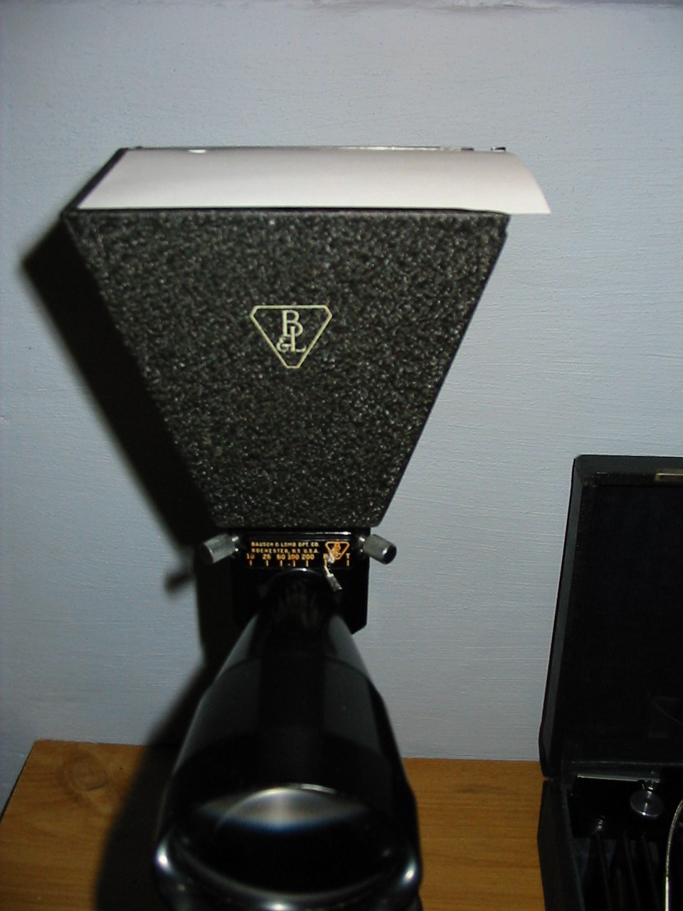
If you’re ready for something more than a cheap plastic magnifier or absolutely need to have more than five diameters of magnification, go ahead and get a Hastings. The larger field of view compared to a Coddington makes them easier to work with and although Coddingtons fill a demand for less expensive higher magnification lenses, a good Hastings is worth the added expense. Always be sure to deal with a reputable dealer who will provide a refund if the optics prove to be poor quality. When in doubt pay a little more and buy from a known manufacturer like Edmund Optics or Bausch & Lomb.

Well, I hope I’ve cleared up a few things about hand lenses for those whose interest in microscopes is just starting, or even old hands who have simply never considered a hand lens as worthy of attention before.