Principle
The logic behind both critical and Köhler illumination deals with an optical formula that proves for optimal resolution one needs to match the optics of the lighting system with the optics of the image forming system. In theory, it would be ideal to use a matched pair of objectives, one for viewing the specimen and the other for illumination. As suitable as it would be optically, one may see any number of reasons why this arrangement would prove prohibitive.
Critical Illumination
Edward Nelson used the optical principles of noted microscopist Ernst Abbe to outline a process of specimen illumination which would come to be known as Nelsonian, or more commonly, critical illumination. A broad wicked lamps flame (a homogeneous light source) was the primary source of artificial light for microscopy in that day. The large evenly lit flame was free of grain and relatively uniform, making the chief disadvantage of the method less troubling than one might expect. It is best to use a ground glass filter or opal bulb to provide a comparably homogeneous light source when one wishes to employ critical illumination today.
Little more than a means of focusing the light source on the specimen, critical illumination is possible with nearly any source of illumination. The microscope must be equipped with a condenser capable of providing a numerical aperture which matches that of the objective to be used. Additionally, that condenser must be focusable-though it does not matter if the range is significant for most arrangements, and provided with a diaphragm of some sort which may be altered to fit the objective in use. When critical illumination is achieved an image of the light source is seen in the image plane of the specimen, and the numerical aperture of the illumination system is matched to the objective in use. Put another way, if one were to replace the lamp with their own eye, the specimen would be seen in focus with resolution comparable to that obtained with the objective. Almost any microscope with a condenser can achieve critical illumination, no doubt one reason for its long-term popularity.
Method With a Diffuse Light Source
- Position the microscope so that the rays from a light source are passed into the optical axis, either directly or with the flat face of a two-sided mirror.
- Using a 16mm objective and 10x ocular bring a stained smear or thin section∗ into focus on the microscopes stage.
- Open the condenser diaphragm fully and rack the microscopes condenser up or down until a clear image of the light source is seen in the image plane of the specimen.
- Remove the ocular and sight down the body tube with the eye positioned ten inches from the tube.
- Stop down the iris diaphragm of the condenser until the back lens of the objective is seen just to be reduced in size.
- Replace the ocular and repeat steps 3-5 whenever the objective is exchanged.
Example A (Diffuse Lite Source)

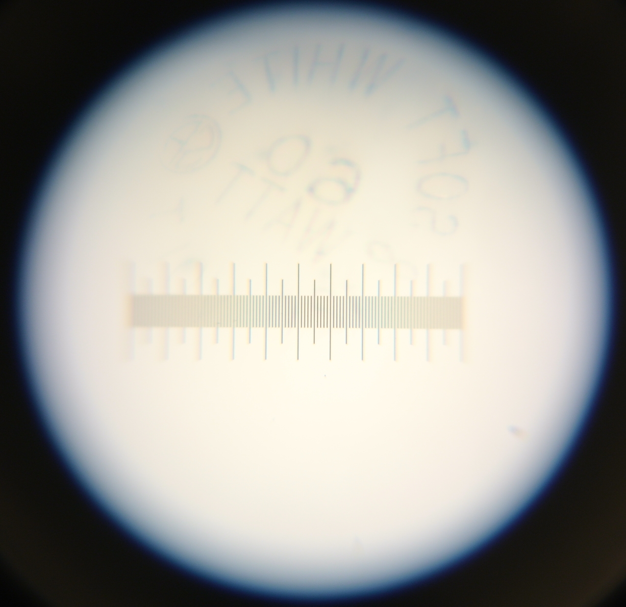
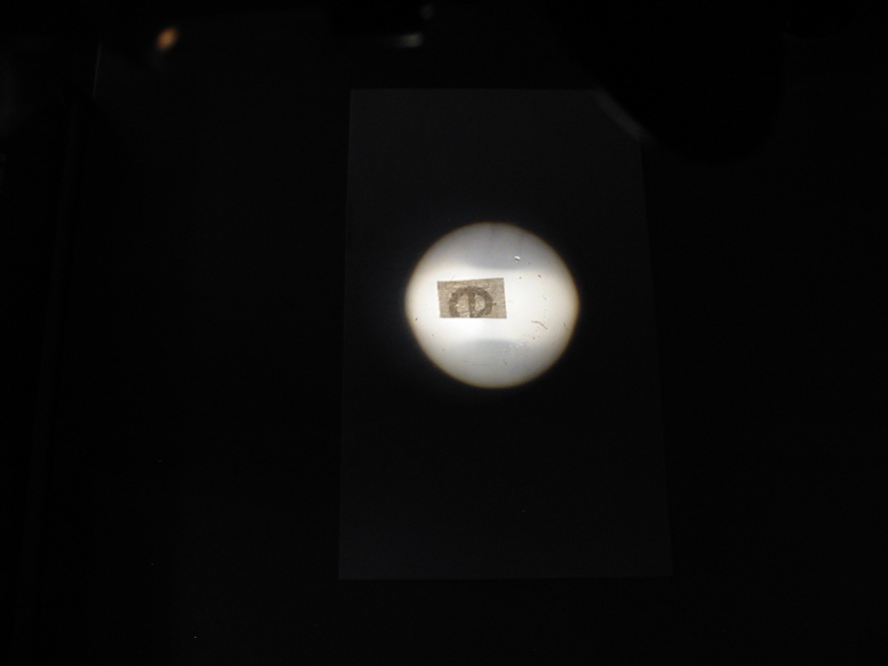
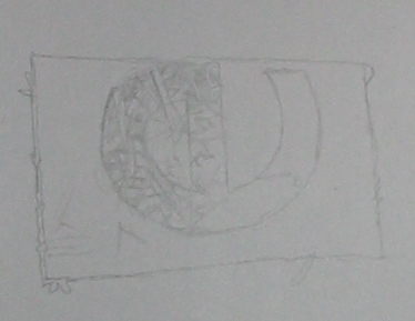
Light source image with critical illumination and frosted bulb.
Above is the eyepiece image as seen when set up for critical illumination using a desk lamp with a standard frosted household bulb. The microscope used had a spiral focusing condenser that provided a movement of less than 5mm. It was still more than enough to focus the lamp which was around 250mm distant from the mirror, the plane side of which was used. One can clearly see the printing on the surface of the bulb.
Method With a Condensed Light Source
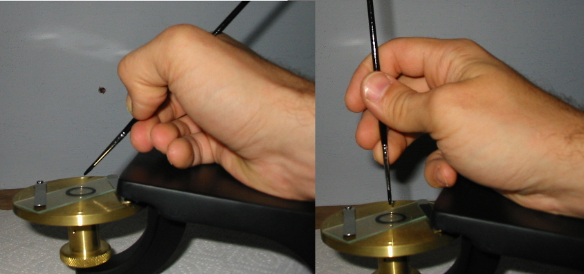
- Prepare a focusing assist, it may be anything from the tip of a sharpened pencil to a dissecting needle. I prefer a small point of card stock with a lightly gummed back.
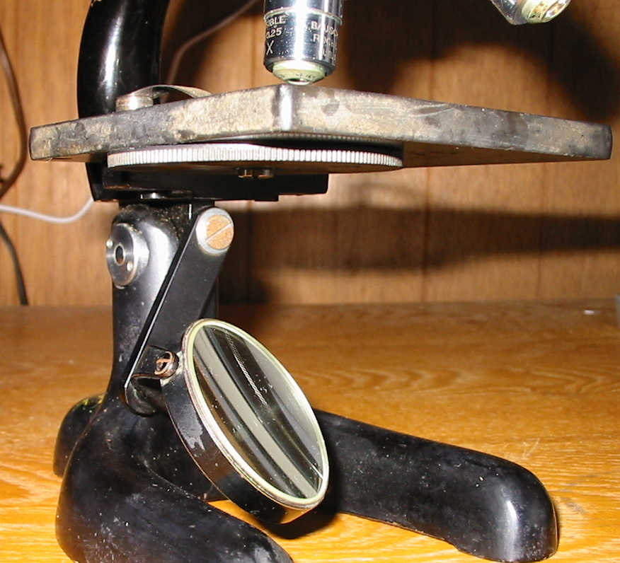
- Position a light source so that the point from which rays emanate† is from six to ten inches from the microscopes mirror.
- Focus the light source so that it projects a lit field large enough to fill the surface of the mirror.
- Arrange the flat face of the microscopes mirror so rays from the light source are passed into the optical axis.
- Using a 16mm objective and 10x ocular bring a stained smear or thin section into focus on the microscopes stage.
- Hold the focusing assist against the point from which the rays of light emanate.
- Open the condenser diaphragm fully and rack the microscopes condenser up or down until a clear image of the focusing assist or light source is seen in the image plane of the specimen.
- Remove the ocular and sight down the body tube with the eye positioned ten inches from the tube.
- Stop down the iris diaphragm of the condenser until the back lens of the objective is seen just to be reduced in size.
- Replace the ocular and repeat steps 5-8 whenever the objective is exchanged.
Example B (Condensed Light Source)

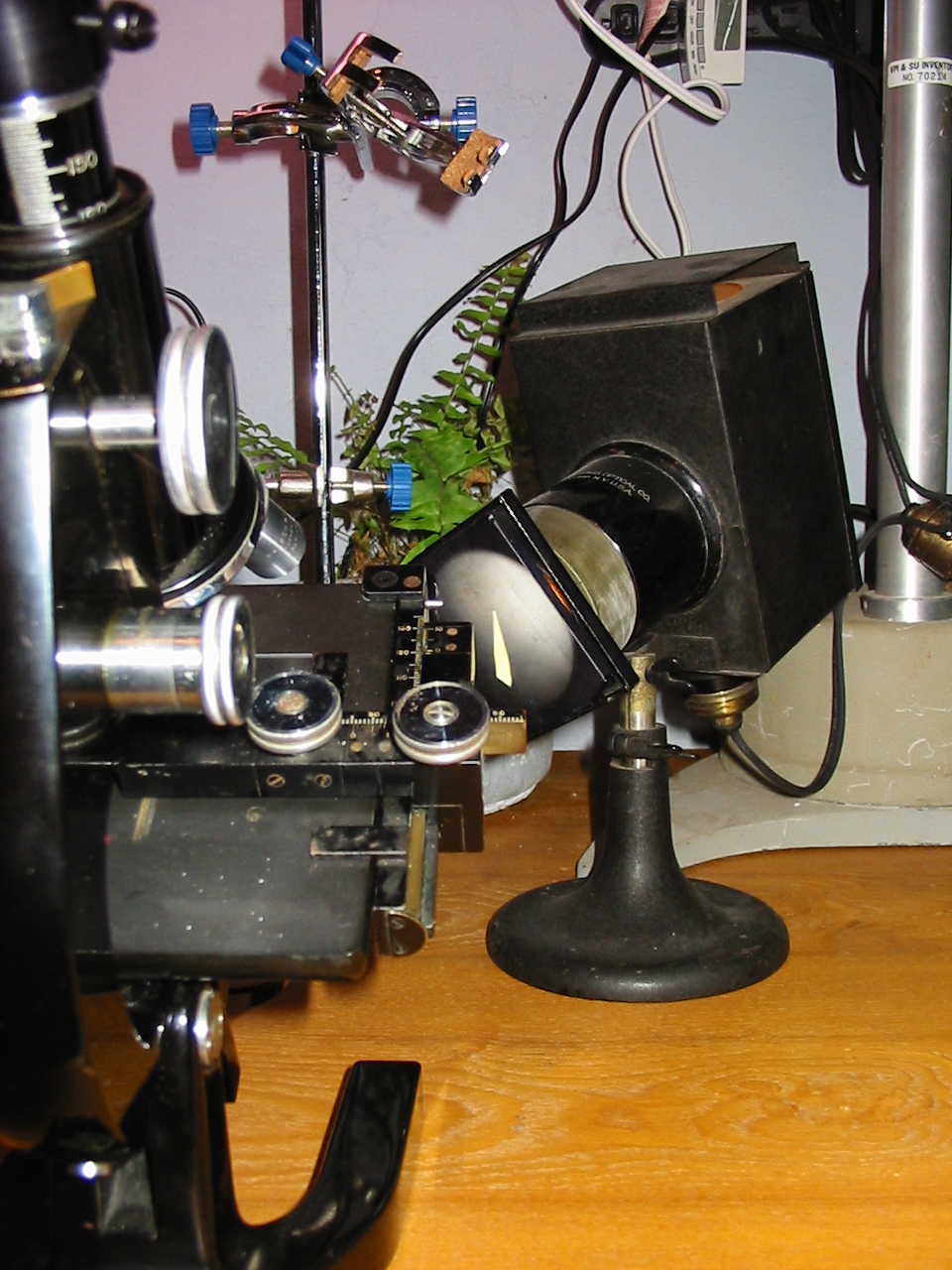
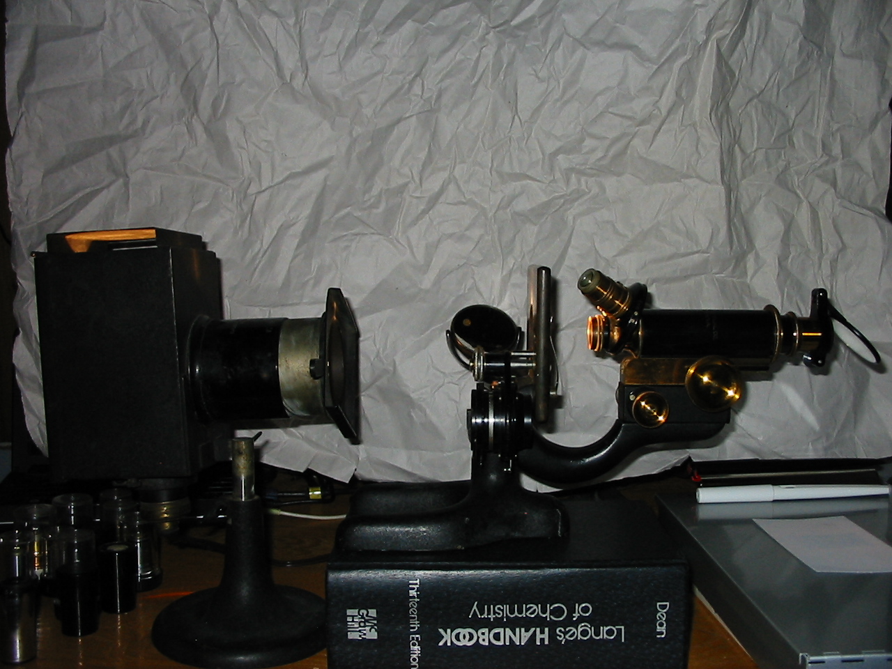
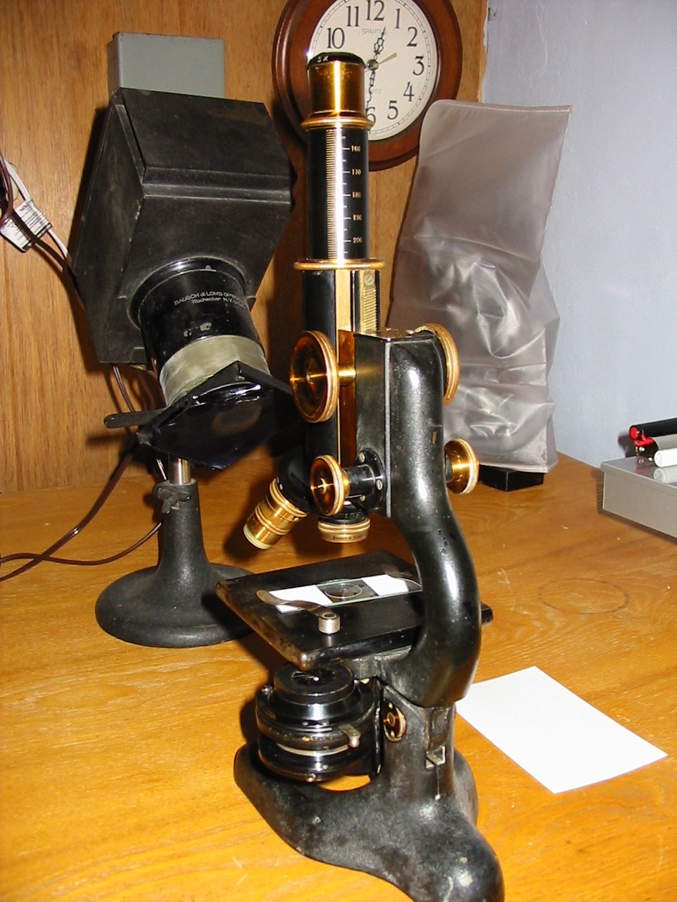
The illuminator with frosted household bulb and ground glass Corning Day-Light filter.
The illuminator was positioned as seen at right. When using a ground glass filter the ground surface of the filter becomes the light source, and it is this surface that must be focused with the condenser for critical illumination. We can use an inexpensive household light bulb, opal bulb, or clear coiled filament bulb without issue. With a clear bulb one can focus on the filament image that shows on the ground glass, without the filament image a focusing assist is essential. The assistance in this case is provided by something I felt people would have on hand; a point cut from the adhesive surface of a Post-it®‡ note. Put it in place for focusing and then remove it or adjust the mirror slightly to bring move it beyond the field of view. Only minor adjustments for alignment, stopping down the iris diaphragm, and re-focusing of the condenser will be required when switching between objectives. Once the illuminators condenser if focused it will not be necessary to re-focus for other objectives provided the distance to the mirror is not changed.
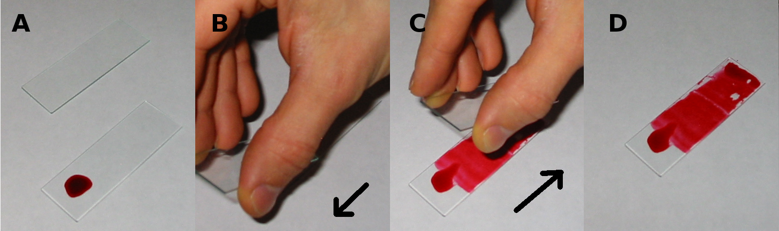
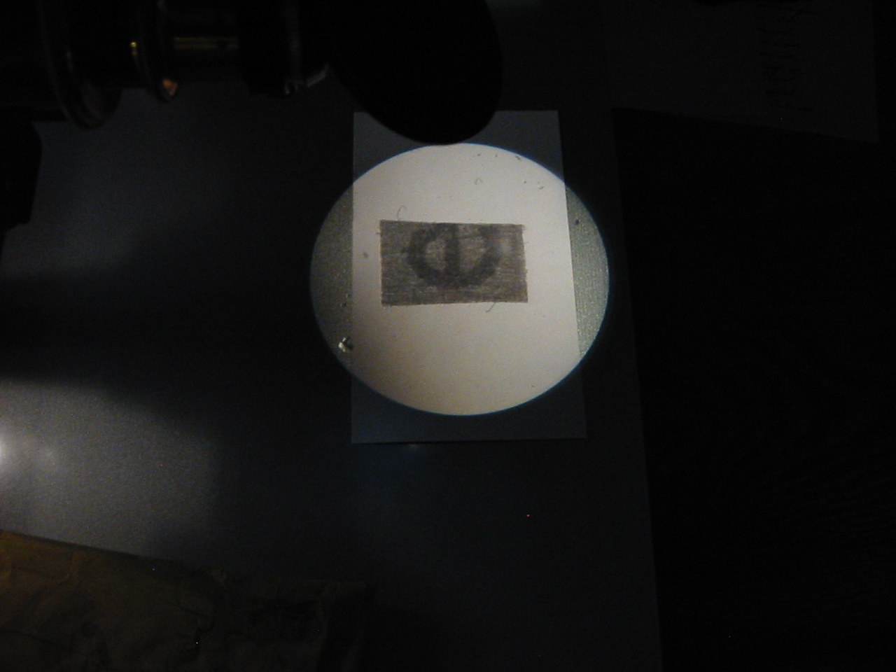
First is an image of the filed of view taken with a 16mm objective and the focusing assist in place as critical illumination is set up. In it one will note the pronounced color fringes on the edges of the focusing assist. The microscope used is equipped with an Abbe substage condenser. Not corrected either for chromatic or spherical aberration, it is the primary source of the fringes seen in the image bellow.

Image of focusing assist in image plane of specimen.
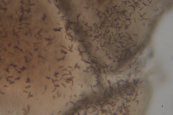
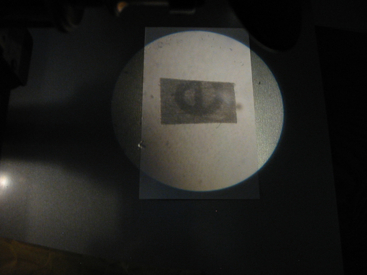
Next is an image of the same specimen, taken with the same set up and without altering the position of the slide. Even with the low quality of the camera system (Nikon 1 J1 positioned with image sensor at eyepoint) one will note that we are nearly able to resolve the Mycobacterium tuberculosis in this stained sputum smear using a common 10x Bausch & Lomb eyepiece and (less common) achromatic 3mm 0.85NA (60x) objective from the 1940’s.

Critical illumination at high magnification.
Pointers
The focusing assist is not always essential, but will greatly speed matters along when using a finely grained filter or opal bulb. Be mindful if one is working with bare bulb or a condensed lamp as the assist and field lens may become quite hot.
If working with lower powers one may need to remove the upper lens of the substage condenser to provide a large enough cone of light for the objective. In some microscopes the upper lens of an Abbe condenser is screwed into the base of the stage (rather than the upper surface of the condenser) and one may need to unscrew and place it on top of the condenser for use with objectives of 16mm. If the image of the light source is distracting it is a better practice to lower the condenser rather than raise it, resolution will be reduced but unless one is working near the limit of the objective it will not be significant.
If one has a condenser that is not equipped with an iris diaphragm (first rail against the manufacturer) then prepare an opaque filter that can perform the same service. A small piece of aluminum foil can be punctured to provide a suitable aperture for a given objective. The diaphragm must be matched to the rear lens of the objective so that the numerical aperture of the condenser is matched to the objective. If used without oil the maximum numerical aperture of any condenser is limited to unity by the refractive index of the air through which the light passes.
Notes:
∗Some swear by the use of a special slide for setting up critical illumination, preferring anything from a cross hair to a micrometer; it has even been recommended that one use a standard slip on which has been scored a line with a diamond or carbide pen. Such slides may not prove sufficient when attempting to focus fine detail at low power. A well stained specimen of uniform thickness will do well in any circumstance.
†For a homogeneous light source this is the ground glass, flame or opal bulb. For a light source with condenser this is the field lens of the condenser. For a light source used in conjunction with a bulls eye lens it would be that lens.
‡I absolutely adore Post-it® notes. As it’s my birthday tomorrow, I really hope someone who’ll be at the party gives me a few packets!
I guess we’ll do Köhler next time; I should have known I’m too much of a chatterbox to get everything in one post! -K