Opaque Object Microscopy part: II

Before looking closely at microscopes which were purpose built for reflected light work it is first imperative that one understands the requirements of such a stand. It must of course allow for some means of illumination, but beyond that there are a few needs that are not so obvious. Consider the compound transmitted light microscope, several aspects of it’s construction are dictated by the optical properties of human vision, a substantial number of others are dictated around changeable constants that are functionally arbitrary. A microscope slide and cover slip that is of a given thickness greatly simplifies the construction of an optical system that will provide an ideal image with minimal and known defects. Furthermore, it dictates that all specimens will be of a consistent and narrowly variable thickness.

Any microscope that needs to accommodate opaque objects will either have to account for the need to examine specimens of unknown thickness or be considered specialized. It need not be overly complex, one could make use of a stand having a significant range of motion in its coarse focus, or possessing a means of modifying its base working distance-as one finds on many stereo microscopes.. A further option would be to articulate the stage such that it may further enlarge the accommodation of the coarse focus. This is a simple mechanical alteration to an otherwise standard microscope foot; as a condenser is unnecessary, the stage is for all intents and purposes mounted to the condenser mount. An inverted microscope forgoes this need entirely by radically re-configuring the entire apparatus, a good investment if only one microscope is liable to be acquired, but it’s worth noting that inverted microscopes are in general far less common on the second hand market and consistently more expensive.

It is also required that the microscope provide for the specialized optics of a reflected light system, namely the light source. In the initial post we saw the difficulty of using a light source external to the image forming optical axis. It is therefore required that the illumination system be congruent with the optical axis. This requires that there will be some additional apparatus placed somewhere in the optical axis, by convention it is generally placed outside of the body, between the nose-piece and the end of the body tube. Whether this is dictated by optics rather than mechanics (or the economics of manufacturing) is unimportant, the result is the same.

At a point in the optical column of the microscope a high intensity light source is introduced. In every example of which I am aware this light source is situated perpendicular to the axis. It is suitably condensed and often fitted with a pair of iris diaphragms (a field diaphragm and condenser diaphragm) as well as filter carrier before being directed down towards the objective via a reflecting surface. A prism or half silver mirror is the usual method; often both are available with the ideal choice being contingent upon specimen and objective.

The actual construction of the reflector is related to the properties of the objective, with all parts involved being of a number of mechanical types. All of the differences in the system of illumination are chiefly concerned with the path of light. There exist two primary types: coaxial and vertical. It’s confusing because few operators, and even manufacturers are careful with their terminology.

Both coaxial and vertical illumination are methods of reflected light microscopy, and coaxial is by definition vertical while vertical is not necessarily coaxial. Coaxial illumination is so called because the path of the light source shares its axis with the path of the image forming rays. The poor mans coaxial illuminator is a flashlight held to one eyepiece of a binocular stand while the other is used for viewing-authors note: don’t do it! The axis of illumination and image formation are one and the same. Vertical illumination is a story of two axes where each is distinct but parallel. The most common type of vertical illuminator is able to provide both methods, but the quality of the coaxial illumination is often inferior when compared to modern outfits designed for coaxial illumination.

Without bothering to get in to dark-field (yes, there are dark field objectives for reflected light work) there are two types of objective one will encounter. The first is essentially no different from any standard objective, excepting of course for differences in the common powers, corrections, and other properties best left for later. The second, and more complex type, is designed to work with a particular type of light source. This second type (which I have always thought of as metallurgical as that is how the BalPlan microscope line of B&L designated them and they were the first I used) caries within its body a transparent glass bushing which extends from the mount to the object lens, surrounding totally and supporting the lenses of the objective. This glass pipe is little more than a means of placing a ring of evenly diffused light on the specimen in a place where the objective itself would obscure other sources. Properly arranged, it is an excellent system and dispenses with much of the glare one will find in poorly aligned coaxial or even vertical systems.

There, next time: photos! -K

Opaque Object Microscopy part: I

I think at this point I’ve been away long enough that this may qualify more as a return from the dead than a return from a hiatus. -K
Most of what anyone at the level of a hobbyist is going to be looking at with a microscope is going to be what is convenient. Now, this is not meant as an indictment, merely a truthful commentary. For the bulk of those with a microscope this is going to mean that what one is going to be looking at is dictated first, by the microscope which is available, and only after by ones interest. When conditions allow this translates to transparent objects for the compound microscope and large opaque objects for the stereo microscope. There are, thankfully, limitless opportunities for the indulgence of ones interest regardless of the microscope which is available.

The next few posts will focus on a category of microscope which is rather less common but is specialized for a particular variety of specimen. The particular type of microscope is rather less common, and one could speculate endlessly on the reasons for this. This microscopist is of the opinion that the reason for this is in general attributable to its being far harder to prepare specimens for a reflected light microscope, than to settle for lower magnification and use a stereo microscope. However, there are a variety of applications for which one will find the power of a stereo microscope lacking. One is then left with the prospect of attempting to so treat the specimen as to render it suitable for transmitted light microscopy, or of finding some way of providing suitable lighting and using a standard compound microscope. Anyone who has attempted to observe an opaque object at high power will understand the difficulty of providing for adequate illumination.

For the sake of completeness, here are the logistics when one is forced to make use of a standard compound light microscope for reflected light work. One might first make use of some small and high intensity light source, employing it in such a way that the termination of the visual optical axis is brightly lit. This is actually surprisingly simple in the present day when an LED flashlight the size of a shotgun cartridge is brighter than any oil lamp. After oil lamps gave way to electric lamps the microscopist was required to somehow retrofit a standard lamp bulb so that it would provide a bright beam of light with no errant brightness.

There was also the possibility of purchasing a small bright light source such as a Nicholas lamp. Although those were surprisingly expensive in their day, they are quite economical now and widely available second hand provided one is willing to type a few searches. Before getting to much farther off topic, do consider picking up a Nicholas illuminator. Color temperature aside, the tight beam is well corrected and the arm most are fitted with is a great asset. Working with a Nicholas lamp and a compound microscope, we will quickly see why this method is far from ideal.

IMGP0005

Poorly set up.

In the above image we can see that a light source is set up sufficient to permit the specimen (here the engraved body of a pocket knife) to be brightly illuminated to the naked eye. There is enough working distance that no significant difficulty was involved in setting it up. A quick look through the eyepieces will immediately demonstrate that this set up is not only far from ideal, but entirely unsuitable. The light source is a painfully bright halogen bulb but the view from the oculars is quite dim, contrast is excessive, and there are visible color fringes even though the lowest powered objective (here a 30mm EF/3.5x achromat) is being employed. Some of these defects can be corrected even in this compromise set up.

IMGP0010

Ideal compromise set up.

In the above image is shown an exaggerated ideal arrangement of the available resources. If one takes the stage for a plain, and draws a vertical line along the visual optical axis the light from the illuminator should be arranged so as to be as at the most acute angle to the optical axis possible. This will go a long way to limiting the extremes of contrast and removing the color fringes. It will similarly  render the specimen as bright as possible under the present conditions.

It may not be immediately apparent but working distance is the limiting factor here. As soon as one moves beyond the 10mm or so that one is afforded by a standard 16mm (10x if you’re more comfortable with magnification than equivalent focus) objective the few working distance of a 4mm (43x) objective is far to short, even that of a rather less common 8mm (21x) objective will be much to short for all but the most intrepid of operators. Then, should illumination be secure one will be presented with a view of such poor quality that the effort is entirely wasted.

Next up… vertical illumination.

Another Entry Level Microscope

The Bausch & Lomb Standard Teaching (hereafter ST) microscope is hardly the finest instrument one may buy, though it is a true and reliable stand. Carrying on the great tradition of simple and rugged construction begun with consumer microscopes designed for both student and arm-chair scientist the ST is descended from the FL (For Learning) of decades prior. For a look at a far earlier version see this previous post.
Immediately recognizable by its B&L slate-gray enamel one will always know an ST or FL upon sight. Telling one from the other is simple as well, meerly glance at the fine focus. If it’s located at the inclination joint it’s of the ST line. A fine focus on the arm above the joint is indicative of the FL line. There are a number of less immediate means of identification, the contruction of the foot, the mechanics of the coarse focus, the presence or abscence of a focusing stop, and the finish of the stage, to name a few. This is about the ST though, so on with that.

As with most B&L lines there are more variations on the basic ST stand than one would expect ranging through optical components to convience features. Apart from the regular ST there is also the Inclined model (IST) which carries a two piece body tube with prisim adjusted angled ocular tube. It’s called the ST for a reason though and the versions that could be had ranged from the very modest too three objective, condenser equipped models with mechanical stages suitable for entry level bacteriology, and other oil-immersion work. The most advanced models made use of the same objectives as the flagship Dynoptic line, their compromise was the slide focusing condenser. A slide focus condenser is not to be sneared at, but when used with an external illuminator one may be hard pressed to secure Khler illumination. Pressing a simple substage to its limits and restricting the user to a monocular system the advanced end of the spectrum is not where the ST shines.

At the lower end one finds the ST in its element. The not quite there, complecated yet inexpensive condenser set up is replaced with a simple rotaing disct diaphragm and either concave mirror or Optilume lamp. It’s worth mentioning that B&L with the ST line once more holds to the concave mirror only (for condenserless substages). The Optilume is well suited too, offering a bright field of view and on/off simplicity.
Perhaps the most laudable feature is one that more advanced users will never make use of. The ST microscopes take seriously the inexpert focusing of the student or novice microscopist. However much one drives home the importance of the microscopists obiesence there are those who will insist upon obtaining coarse focuse with eye at the lens, all such marksmen should be forced into carears as snipers. The ST line repesents the first standard Prefocusing Gage from B&L.

This simple addition has doubtless saved more than a few slides from the hazards of crashing objectives. The Prefocusing Gage is a humble projection from the body tube through which a theaded hole has been bored. A hexagonal set screw is fitted through the hole and a smaller flat headed set screw penetrates from the side to lock it in place. In use one need only to place a slide between the gauge and arm and gently rack down the coarse focus until contact is made. Removing the slide to the stage one will then find the specimen in rough focus and need only touch the fine focus knob until examination is complete. As with most every microscope of quality the objectives are parfocal so the utility of such a device should be obvious.

If one has other stands at their disposal one may see quickly where costs have been saved on the ST microscoscopes. The fine focus mechanism is mechanically identical to that of the Dynoptic but there is not graduation upon the adjustment. The body tube has been cast from a single mould so that nosepiece and ocular tube are permanently in place. The stage likewise is cast as one with it’s mount and may not be exchanged without likewise replacing the entire substage.

For those people out there who have and use an ST or IST here are some useful measurements from the manual (I’ll get around to uploading a scanned copy of it sometime).

First the table of approximate equivalent size of the pointer in the plane of the specimen:

Then the table of magnifications with the same 10x Huygenian eyepiece:

What Happened to Spring?

Here we are enjoying the second week of the spring season and yet again, it’s snowing. -K

Spring is easily among the most productive seasons for the nature microscopist. Freshwater diatoms are at their peak in the spring, and many insects that have overwintered are out, as are the various forms that hatch as the weather warms. If there is a body of water a convenient distance from ones base, it can be very educational to chart the rise of spring by each day doing a quick survey of the contents of a drop of water. Does the density and variety of microbes rise steadily with temperature? Does it fall or continue to rise as snow-melt dilutes the body of water with a seasonal influx? Or does it just keep snowing!

Note the artifacts around the arrow.

Note the artifacts around the arrow.

Above is an image taken of a preserved snowflake. It is not a very good preparation but illustrates a couple points that should be emphasized. Firstly a bit of information on the preparation itself. Snow was allowed to fall on a clean slip and over a likely specimen was dropped a solution of polyvinyl formal. Without the addition of a cover glass it was maintained at a freezing temperature for a few minutes as the resin formed a cast of the captured ice crystals in a gas permeable clear plastic. When brought indoors the water from the ice crystals was able to evaporate leaving a hollow shell that may be observed.

At the tip of the arrow we observe a large air bubble. As a result of the method of preparation the air bubble formed because of air trapped in the resin itself. The large size of the air bubble makes its identity obvious and more of a nuisance than a distraction. To the left of the arrow we see an additional bubble much smaller in size. Such bubbles will spoil any preparation but illustrate an important lesson concerning depth of focus and optical alignment very well.

In the above image the small air bubble presents with a distinct black outline. This black outline is too large to illustrate diffraction rings well, but that is the principal behind much of the following. The black portion is caused by stacked layers of out of focus image planes. As a result of the known shape (spherical, with some distortion) of air bubbles we can easily picture it in cross section, the optics of out microscope can not however provide a clear outline of the section because the layers above or below obscure the image.

The top aspect of the bubble in focus.

The top aspect of the bubble in focus.

Increasing the magnification we can easily bring the top aspect of the bubble into focus. The black outline then becomes an aid in determining the actual form of the bubble. If our lighting is truly central we are able to discern that the portion of the bubble nearest the pointer is thicker than that which is farther away, as evidenced by the more pronounced black fringe.

If our lighting is not central then we can use the bubble to determine in which direction to move our condenser to bring it into alignment. In the above example we might take the lighting as generally central, which we can tell by observing the black fringes on the larger air bubble. However, to be truly accurate we can observe that there is a very light fringe just inside one edge of the larger bubble. Adjusting the condenser a very minor amount in the direction opposite that fringe we are able to obtain more perfectly aligned illumination.

Our condenser properly aligned provides axial lighting.

Our condenser properly aligned provides axial lighting.

Although still not entirely axial we observe that the fringe is much less in evidence. Properly aligned illumination is vital to correct interpretation of the image. We can now form a more accurate mental image of any object we elect to observe simply by sending the fine focus just above or below the image plane we wish to observe. Axial lighting provides that any dark fringes we observe will be a product of the specimen rather than an artifact of our illuminating system.

Determining Objective Magnification

Here’s hoping this is useful as more than just an academic exercise. -K

In the previous post we looked at equivalent focus as it relates to the power of an objective. It was noted that the power marked explicitly on ones objective is sometimes at odds with that implied by the equivalent focus. Today we’ll look at one way to determine the actual power of a given objective. The method used is among the more equipment heavy, but it is also one of the least demanding so far as manipulations go.

One will need the following:

  • A microscope with a draw tube (or an eyepiece collar)
  • A 10x Huygenian eyepiece
  • A 10x Ramsden eyepiece
  • A stage micrometer
  • An ocular micrometer (installed in the Ramsden eyepiece)

Method

Using the Huygenian ocular, with the stage micrometer as an object, and the draw tube set to the length for which the objective is corrected (160 in most cases) the objective to be measured is brought into sharp focus. The Huygenian ocular is then replaced with the Ramsden and everything brought into sharp focus by moving in or out the draw tube. One must not focus using the microscopes coarse or fine adjustments.

Line up the rulings of the stage micrometer so that a given number corresponds with a particular span of the rulings on the ocular micrometer. Be sure that the rulings are lined up consistently, do not measure from the outside of the line in one place and the inside in another. Use as much of the available rulings as possible for increased accuracy. Write down the rulings on the stage micrometer that are required and the corresponding number from the ocular.

Now divide the distance of the rulings on the ocular by the distance of the rulings on the stage. The dividend is the ocular independent magnification of the objective.

In Practice

A stage micrometer is measured against the Ramsden micrometer eyepiece as described above. Rulings on the stage micrometer are .01mm apart and rulings on the eyepiece micrometer are .1mm apart. It is found that 95 rulings on the stage micrometer correspond exactly to 98 rulings on the eyepiece micrometer.

9.8mm / .95mm = 10.3

The objective then, provides 10.3X magnification.

With a different objective it is found that 15 rulings on the stage micrometer correspond to 65 rulings on the eyepiece micrometer. Once again we work in consistent units of measure.

9.3mm / .22mm = 42.27

The objective then, provides 42.27X magnification.

In Theory

Some users may immediately wonder why it is emphasized that one must focus with a Huygenian ocular, only to replace it with a Ramsden fitted with a micrometer, and manipulate the draw tube for focus. Why shouldn’t one simply use a Huygenian ocular fitted with a micrometer? After all it works for measuring structures.

First consider the construction of a Ramsden ocular. The positive ocular forms a real image below its field lens, outside of the influence of the oculars magnification. A Hugenian ocular, a negative ocular, only forms a real image after light from the objective passes through its field lens. The upshot of which is that a Huygenian ocular will measure an objective as more powerful than it is.

Why then does it mater if one focuses with a negative ocular like the Huygenian but measures with a positive ocular like the Ramsden? The simple explanation is that doing so negates the magnification that results from the eye viewing a virtual image on which a real image of a ruled reticule has been overlaid. Using the Ramsden only will again result in a distortion of the objectives power.

Notes:

∗An eyepiece collar is a small, friction fit, split disc which rides around the outside barrel of an eyepiece and prevents it from seating fully into the microscopes body tube. Such a collar can provide a microscope not equipped with a draw tube with much of the same functionality.

†A Huygenian filar micrometer used with the objectives above measures their powers as 11.37X and 47.8X respectively.

‡In this case the Ramsden eyepiece alone measures the objectives powers as 10.2X and 43.3X. These distortions represent the degree to which the focus was adjusted by manipulation of the draw tube after switching from the Hugenian ocular to the Ramsden.

Good Practice with the Student Microscope

Parts of the following are good practice with any microscope, it’s hoped those who find the rest dull will know the difference. -K

General Preparation

In preparation for a little time at the microscope one should first set their table in order. If more then one ocular is possessed it should be brought out, together with the specimens to be examined. One should have at hand a paper and pen, on the chance that a note or a sketch will need to be made. A lamp should be on the table as well, a simple desk lamp with a whitened bulb will do (no bulb with a visible filament will do with a student microscope). If it does not command the table when not in use, the microscope should be brought out or otherwise uncovered and given a quick dusting to remove any that might have settled.

Whether one chooses to work seated or standing, the height of the table (and stool) should be modified for comfort while working. Because one is unlikely to spend considerable time at the eyepiece if uncomfortable, it is important to incline the microscope and arrange the table specifically for comfort. An arrangement that seems comfortable yet results in an ache after prolonged use should be modified in the future. Do not persist with an uncomfortable set up out of convenience or stubbornness. In the below photograph one may be startled to see the closeness of the microscopes foot to the tables edge. This arrangement is that found most comfortable for the writer; with only the writing hand in position to rest upon the table, no stiffness develops across the users shoulders even after several hours.

Layout for general use.

Layout for casual use.

When the lamp and microscope are in readiness one may turn on the light and begin orienting the illumination. When working without a condenser only the concave mirror will provide plentiful light from a convenient source. The distance from the lamp to the mirror is not critically important and will be suitable from 10 to 15 inches(25 to 40mm) provided that an excessively low powered objective is not in use. If one makes use of a 48mm objective (for example) it will be necessary to move the lamp closer to the microscope so that an evenly lit field will fill the eyepiece. Smaller or larger size bulbs than are standard will require the lamp to be closer or farther.

General Practice

Placing a slide upon the stage is a simple thing when no mechanical stage is in use. It is surprising then that so many go about it in a manner liable to damage both slide and spring clips! A slide should be slid into the open space next to the posts by which each spring clip is held to the stage. Once there it is gently pushed up into the area where the clips contact the stage. The slide is now held firmly in place and no undue tension or stress has been or will be placed on either slide or clips. It should never be necessary to pry up the end of a spring clip.

Move the slide in from one side, then slide it up.

Move the slide in from one side, then push it up till held by the clips.

With the slide in place one should look askance at the stage and objective while racking down to within the working distance of the objective. The student (and an astonishing number of very advanced users) would do well to remember that the equivalent focus marked on the objective is not the working distance. As a general rule one may bring the objective as close as one may with the coarse focus when observing from the side, even when it is known to be too near. Upon next shifting the eye then to the ocular one may rack up with the coarse focus confident that the proper focus will be found.

Once the microscope is focus in a general way certain aspects of contrast will have to be addressed. Remove the eyepiece and with the eye located ten inches from the tube sight down the body of the microscope. The user should then select the diaphragm aperture that obscures the outer third of the brightly lit rear lens of the objective in use. Some sources will recommend the obstruction of only a quarter or as much as two thirds of the objectives rear lens. Although in many respects the proper aperture for the best resolution and contrast is dependent on the optical system, when using a concave mirror (and of course no condenser) it is less critical.

Proper lighting being now secured the user may replace the ocular and set to work in earnest. The slide may be moved about as required and the fine focus may be continually manipulated one way and the other to provide a better understanding of the observed structure. Should observation with the second objective be required only the fine focus will require manipulation to find focus however, one should always observer from the side when moving from a lower to a higher power. With any change of objective it will also be necessary to again determine the correct aperture§ to employ as described above.

Notes:

∗In theory, parallel rays of light traveling from an infinite distance strike the mirror and are focused into a cone of light that converges in the image plane of the specimen. One then may imagine that a ground glass (or paper screen) might be placed in the path of that cone and raised or lowered to determine the focus of the concave mirror. This is only effective as an exercise if one is using daylight (genuinely parallel rays of light) as their light source and the mirror in question is parabolic rather than spherical. Because the mirror is apt to be a concave spherical section, the light will not focus to a single point. Those who love geometry might like to calculate some conic sections…

†Even when using slips of non-standard size it is advisable to employ a variation of this method (or employ larger stage clips) rather than bend and potentially deform the clips or create a situation in which they may spring down upon a slide. For a long while it was my practice to forgo the use of spring clips entirely when using the microscope vertically, after much manual micrography I am now so much in the habit of leaving them in place that the absence of spring clips is intolerable. I would recommend any newcomers to use spring clips whenever present and avoid the little frustrations of jostled slides.

‡So very much effects the working distance that it is often only looked at in a very general way, this is no exception! Second only to magnifying power, (higher magnification equals shorter working distance, how much shorter relates to how that higher magnification is obtained) working distance is closely related to numerical aperture. A 10x objective of 16mm equivalent focus having a numerical aperture or 0.25 will have a shorter working distance than a similar objective with a lower numerical aperture. Remember if one wants higher resolution, one must pay the price for it, both financially and with a shorter working distance.

§If one always employs a similar distance to the lamp and inclination of the microscope the optimum aperture will remain the same for each objective and sighting down the tube with the ocular removed will be unnecessary. For this reason alone a disc diaphragm should be considered a positive feature. The is no significant gain in ability to be had by having an iris diaphragm microscope without a condenser.

The Student Microscope

I was never particularly fond of it being called an elementary or a freshmen microscope, but call it as you will. -K

A B&L student microscope, as fine a stand as one needs for routine use.

As fine a stand as one needs for routine use.

Its Character

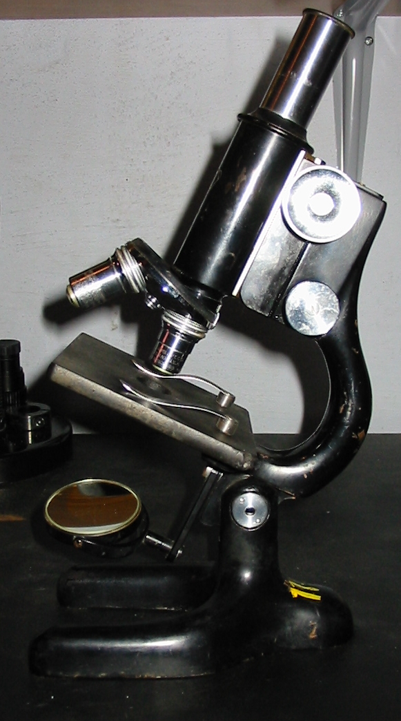
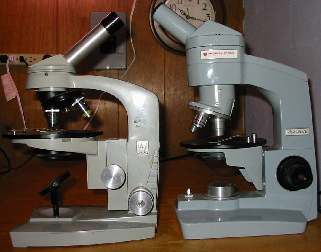
A student microscope is generally simple, rugged, and basic. Where a more advanced stand will have stops and set screws, adjustments upon adjustments, and provision for all manner of accessories, a student microscope will be without. The photograph today shows a representative microscope of the type by Bausch & Lomb which dates to approximately 1930, this particular example saw service at the University of Kentucky school of zoology.

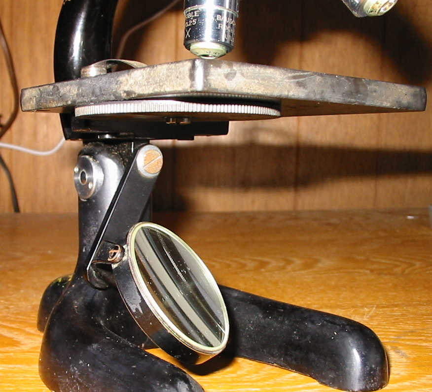
It has the usual things, coarse and fine focus, rotating nose piece with RMS threads, stage with stage clips, inclination joint, rotating circular substage diaphragm, and mirror reflector. At first glance except for the absence of a substage condenser one might be forgiven for taking it as fully as complex as any microscope of the period. However, a brief look shows that this is not the case. The substage mirror is only single sided, and that single side is the a secondary concave reflector. A moment of manipulation will show that the mirror is mounted an arm and post with no positioning stop to provide confirmation of when the arm or mirror are aligned vertically.

There is no provision for the use of filters between the light source and the object. No mechanical stage is present and as a result of construction one can not be conveniently attached. The stage itself, and the microscopes foot are sure to seem small to those accustomed to more contemporary stands, and it is on the smaller side as microscopes go when compared to more advanced stands from the same period.

Its simplicity

Unlike even moderately more advanced stands, the fine adjustment has no provision for measurement. Where a more costly stand will show markings on its fine focus so that a specimens or structures thickness may be measured in divisions of a few microns or less, on the student stand there is only bare metal. One might think this is done to save time in manufacture, a graduated knob surely taking longer and costing more to produce, but it is more complex (or rather less). The fine focus on a more advanced microscope is graduated as a feature, because it can be. It is constructed in such a way that from its lowest to highest limit a a turn of the knob of a given distance will result in a consistent amount of upwards or downwards focus. A student microscope will often show a variation in its vertical travel as one moves through the range covered by its fine focus.

Without a substage condenser there is no reason for a complex external illuminator. Most students misuse both condenser and illuminator even under the watchful gaze of their teacher so doing away with both is as much a matter of efficacy as it is of economy. The rotating diaphragm is mechanically very simple and prevents as much as it may the abuse of the diaphragm to control light intensity as well. Without a condenser the concave mirror alone will serve effectively for the provided objectives.

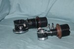
Only two objectives are apt to be present on a student stand. The powerful 43x will operate at the limits of its ability with the mirror and a properly positioned light source. The 10x is likely to be one of the divisible sort that may have its front lens removed so the base may serve as a 32mm objective. Once chief characteristic of proper student microscopes (worlds apart from toy microscopes) is standardization. The objectives on this economical Bausch & Lomb unit are identical to the standard compliment of achromats provided on much more expensive models. The oculars as well are identical to the usual Huygenian sort although, only the 10x is apt to come standard. An educator might have easily purchased a number of 5x, 12.5x, a set of wide field oculars, or a few filar micrometers to share out among a class as required. Todays user might easily find replacements for damaged optics or a variety of oculars to suit their needs.

Its Ability

One might expect that an elementary microscope will only provide passable images. As the objectives and oculars are identical to those of much more advanced microscopes, and complex substages are often operated such as to be useless, there is no reason to achieve less than excellent results with a simple, economical§, students microscope. Given the choice of a students microscope from the 1930’s and a students microscope from today one will find the vintage microscope fully as capable and more deserving of ones time.

A contemporary students microscope is apt to be targeted in its selling points not towards the institution, but rather the inquisitive student themselves or more likely the students well intentioned parent. This has led to a focus on magnification as a selling point and a certain degree of complexity being mistaken for capacity. One will find microscopes offered for student use with three and even four objectives, two and three oculars included outright, complex substages and “focusable” LED illumination.

With fewer optics to choose from one is limited in their choices for magnification, and far more likely to make the correct choice. In have a less complex microscope one has perhaps less opportunity to get into bad habits and certainly less capacity to decrease the quality of the image formed by improper disposition of the instrument. At the simplest a students stand should be able to immediately form an intriguing image for the user. With this old soldier one need only turn on a desk lamp, position the mirror to direct a cone of light through the stage, place a slip under the clips, and (due time taken to perform the microscopist’s obeisance) turning the focus knobs bring something interesting into view.

In a moment a world can be revealed, shown with fully as much clarity as any microscope apt to find itself in a students hand. The work that has been accomplished on such microscopes would stagger in its scope and quality. A simple compound microscope suitable for common use in all but the most exacting applications, the classic students microscope is as useful today as it has ever been.

Notes:

∗Secondary reflectors are much more common than primary reflectors. On a secondary reflector one reflecting surface is covered over by a second (generally far less) reflective surface. A polished metal mirror is a primary reflector, a reflective surface covered by glass is a secondary reflector. Secondary reflectors are inherently imperfect and may result in a ghostly secondary reflection in the image plane.

†The size of the stage and foot will not seem out of place to those familiar with microscopes from the turn of the century. The trend towards larger stages and very large footprints is considerably recent as far as microscope evolution goes.

‡It is not very uncommon to find a microscope of over well over one hundred years age the fine focus of which is as tight and responsive as the best microscopes of today. Many different fine focus mechanisms exist and the best of them are simple (comparatively speaking) and reliable in a way that compares favorably to those of today. They might not impress a watchmaker, but any machinist will find them beautifully constructed.

§In this post I switch at times when writing, between how the microscope might have been employed when new, and how it might be used today. When I describe it as economical it applies both to when it was new and even more so to its value now. The microscope pictured cost me less than twenty (US) dollars and is not some rare and seldom available specimen. In the right hands a microscope of this sort will provide results consistently superior to a modern entry level microscope that commands a price ten times higher.

‖Never mind the correct or most suitable magnification for owns aims, one is apt to spend far more time looking at things and far less time twirling the nosepiece about like a maniac. I see “student” microscopes offering 40-1000x 40-2000x and want to have these charlatans arrested! But then what was I saying about maniacs?

¶A modern student might be troubled first by the hunt for appropriate batteries or power cords, potentially difficult to obtain replacement bulbs and even electrical adapters. With the lighting secured but before placing a slide upon the stage, they must puzzle out the usage of the stage clips; as those on modern stands seem to have been designed by persons with no knowledge as to how they are employed! Then the proper objective and eyepiece must be determined or as is far more likely chosen at random. By this time if interest has not waned they must fiddle about and focus and image that is apt to prove far to highly magnified for their use (beginners have a not unexpected tendency to select powerful magnification initially) and will likely mangle a good many covers and slides in discovering how short the working distance of a high power objective is.

Practical Alignment: Objectives

Objectives are too sensitive to be manhandled by the novice, their mounts however… -K

Modern stands, particularly those intended for student use, at first seem to lack provision for adjusting the objective to improve alignment or centering. This is not any great failure, quality manufacturers produce stands that are near enough to alignment as designed that they might suffer a large amount of mishandling. If one is using a new stand, adjustment will likely be unnecessary. If one has a used stand, one should first check their alignment before making any adjustment. Luckily, identifying misaligned objectives is a simple matter.

All but the oldest and most basic stands will have a simple provision for rapidly changing objectives, a rotating nose-piece is most common. Such a nose-piece provides a rapid method of identifying if alignment is acceptable or not. To make the determination one need only place a prepared slide (a stained blood smear is well suited to the task as one may position an easily recognizable white blood cell in the center, a stage micrometer or other calibration slide would also be highly precise) on the stage and bring it to sharp focus with a particular objective. One will then take care in positioning just in the center of the field of view some conspicuous portion of the specimen. Upon switching to the next objective in the changer the conspicuous portion of the specimen would ideally be still in the center of the field of view, it is never likely to be so.

Perfection of positioning from objective to objective would only be possible should each individual optical component (every lens from light to eye) be precisely centered. Considering the number of individual lenses in each objective, one must accept that if the conspicuous portion is still in the central area of the field of view, the objective is centered. In figure one below, where circle A represents the field of view, one might be satisfied if the conspicuous object remains within the area of circle D from objective to objective.

IMG_1540scalecrop

Fig. 1

There are rotating nose-pieces where each objective mount is fully individually center-able, but they are few and far between; look instead to see if some less exact provision for adjustment is provided. On the Bausch & Lomb nose-piece seen below are small adjustable plaques that serve as positioning apparatus unique to each objective. Moving the position of the plaque moves the location at which the objective stops along arc B-C as depicted in figure one. Although it will not truly center the objective it can be used to position the circle D for each objective along arc B-C.

Positioning plaques and stop.

Positioning plaques and arm stop.

On many other rotating nose-pieces, plaques of the above sort are lacking. However, they operate on the same principle and the arm may be adjusted to achieve the same effect.

A final word of caution, one should focus on achieving the most perfect alignment with the most powerful objective one intends to use. By virtue of having the smallest field of view the most powerful objective will be the one most sensitive to adjustment.

Practical Alignment: Illumination

The terrible thing about an occupation is it’s tendency to occupy; leaving so little time for avocation. -K

One may notice that there are all manner of microscopes on offer, in seemingly endless arrangements. Over time the form of the microscope stand has changed dramatically. For evidence of this one need only browse through the various introductory texts that have been used over the years. Such texts nearly always include a diagram of the microscope and the path of light through the optical components of the same. As much as the diagrams have changed, it never more dramatic than when electric illumination became commonly built into the base of the stand.

For the task today one may divide all microscopes into two very broad groups, those with permanent pre-aligned illumination and those without. In nearly all cases this will mean referring to a stand having an integral lamp such as the AO One-Sixty seen on the right below, or one with a mirror for reflecting the light from an external source into the optical axis as on the AO (Series 2?) seen on the left. In the AO One-Sixty, alignment is taken care of by the manufacturer. One will never need to perform any alignment at all unless of course one suspects something has gone amiss, but more about that another time.

External on the left, internal on the right.

External on the left, internal on the right.

For now we are concerned only with stands having external illumination; those with a mirror. With few notable exceptions the microscope will undoubtedly have a round mirror with two reflective surfaces, one concave and one flat. On the AO (series 2?) the mirror is mounted directly below the fixed condenser. On more traditional stands the mirror is apt to be mounted on a horizontal post that extends under the stage. This post may be mounted horizontally from the vertical portion of the foot which extends beneath the stage, or on an intermediate vertical post which allows for lateral movement; as seen below on this 1940 Bausch & Lomb students microscope.

Swing arm mirror mount

Swing arm mirror mount

There are specialized apparatus and methods of illumination intended for achieving proper alignment of the microscope. Such methods may be time consuming and impractical, particularly when one is unable to leave the microscope set up indefinitely for use when needed. Practical alignment may be thought of as rapid or “quick and dirty” alignment and although imperfect (hardly suited for exacting and critical work) ensures visual accuracy and greatly reduces optical strain.

No special apparatus is required apart from a prepared slide of a stained smear or cross section of uniform thickness. The process takes advantage of the changes observed while working through a range of focus, so it is important to use a slide with an object of uniform thickness. One may employ an ocular of any power and all but the lowest (48-24mm) powered objectives. It is recommended to begin with a 10x ocular and 16mm objective.

Prepare for the process by first setting up the external light source and positioning the mirror to direct a beam of light through the objective and into the eyepiece. If one does not have a condenser and has the option to use a flat or convex mirror, select the flat mirror for use with any objective of more than 4mm (43X and below in general practice).

The Process (with a condenser or concave mirror)

  1. Position the prepared slide upon the stage and bring the objective into focus with the coarse adjustment knob.
  2. Looking through the ocular work the fine adjustment through focus so that one can observe both the lowest range of focus and the highest.
  3. Notice that one small area comes into focus first as one focuses down, and leaves focus first when focusing back up. That area is the location where the light from the condenser is converging.
  4. Adjust the position of the mirror so that the location where light from the condenser is converging is in the center of the field of view. When the area is in the center the illumination is aligned or axial.

The Process (without condenser or concave mirror)

  1. Position the prepared slide upon the stage and bring the objective into focus with the coarse adjustment knob.
  2. Looking through the ocular work the fine adjustment through focus so that one can observe both the lowest range of focus and the highest.
  3. Notice that focus tends to progress from one area of the field of view to the next in a wave. Without an optical surface converging the light (as a concave mirror or condenser would) alignment is reliant on parallel rays of light.
  4. Adjust the position of the mirror so that the center of the wave of focus appears as a ripple extending from the center of the field of view (caused by spherical aberration in the objective) rather than a wave from one side to the other.

The process may seem tedious at first but skill is rapidly acquired. If the concept seems unclear sketching out the rays of light on a sheet of paper quickly explains the variation caused by improper alignment and is quite straight forward.