Elucidating Illuminators: I

Integrated Illumination

The choices one has in microscope illumination are often, of late, made by the microscope manufacturer. That choice is not always the one that the user would make for themselves, or even the best for general use. In general one might say that with integrated illumination, whatever the quality, age, or price of the microscope, one can rely on prompt success when it comes to simply obtaining an image. The perfectness of that image may range from excellent to abyssal, but something will certainly be seen at the eyepiece.

Today, if one is possessed of a microscope with integrated illumination little need be done for acceptable operation. A microscope equipped with a mirror is as easy for general, but more complex for critical work, when compared to a stand with integrated illumination. The mirror microscope is next to impossible to use at its full ability without a measure of effort and understanding of some of the methods of illumination for transmitted light microscopy. Let us begin by looking first towards a number of microscopes equipped with integrated illumination of various sorts and speak to the merits and abilities of each.

Köhler Illumination with the BalPlan

IMG_1656rotatecropedit
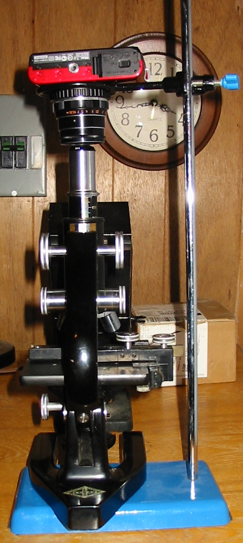
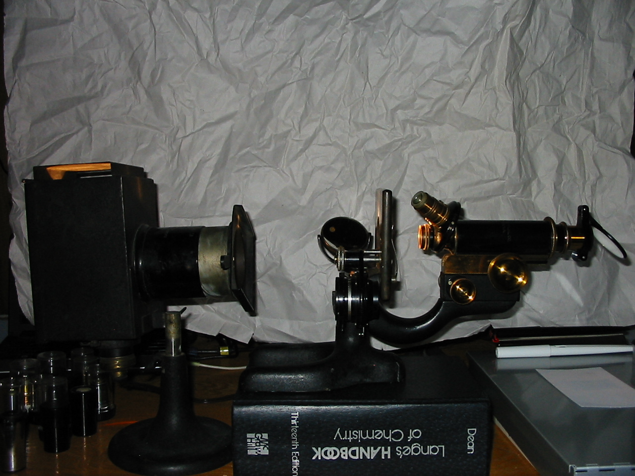
This model of the Bausch & Lomb Balplan uses a halogen lamp mounted in the base to illuminate a ground glass Plano-convex lens secured in the base. From there, a beam is sent through an iris diaphragm and fixed focus lens towards a right angle mirror which sets the light vertically through a second lens. The coherent light which emanates from this lens is then passed through the microscopes rack and pinion 1.25N.A. aplanatic condenser. The condenser is equipped with an auxiliary lens which may be swung into place to expand the pencil of light and provide a large enough light source for use with a low power finder objective.

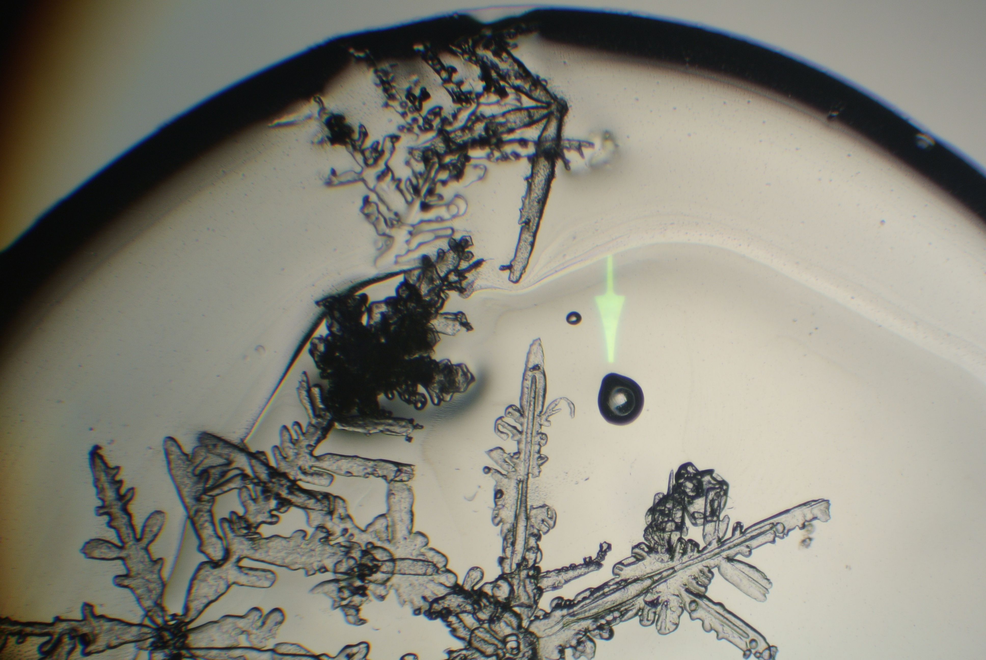
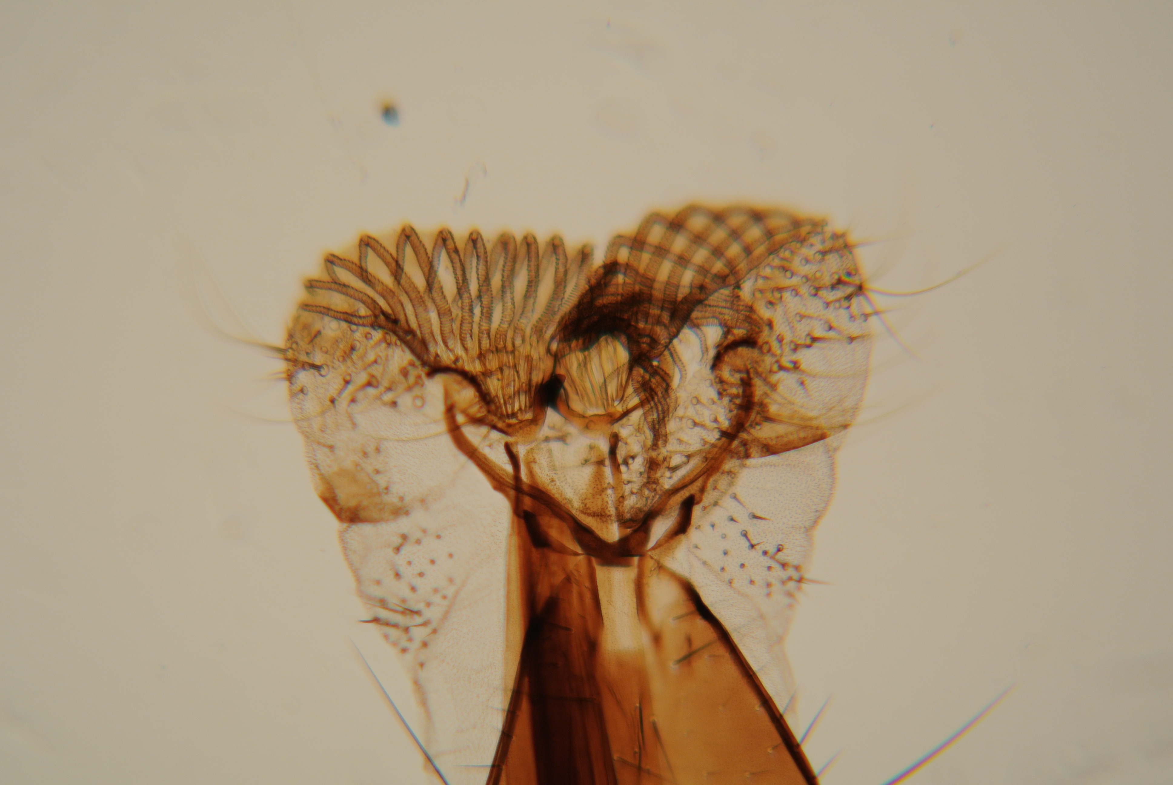
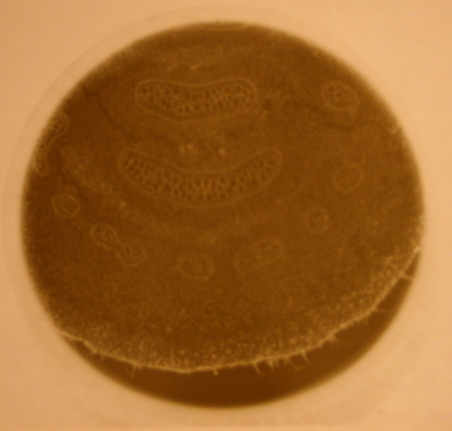
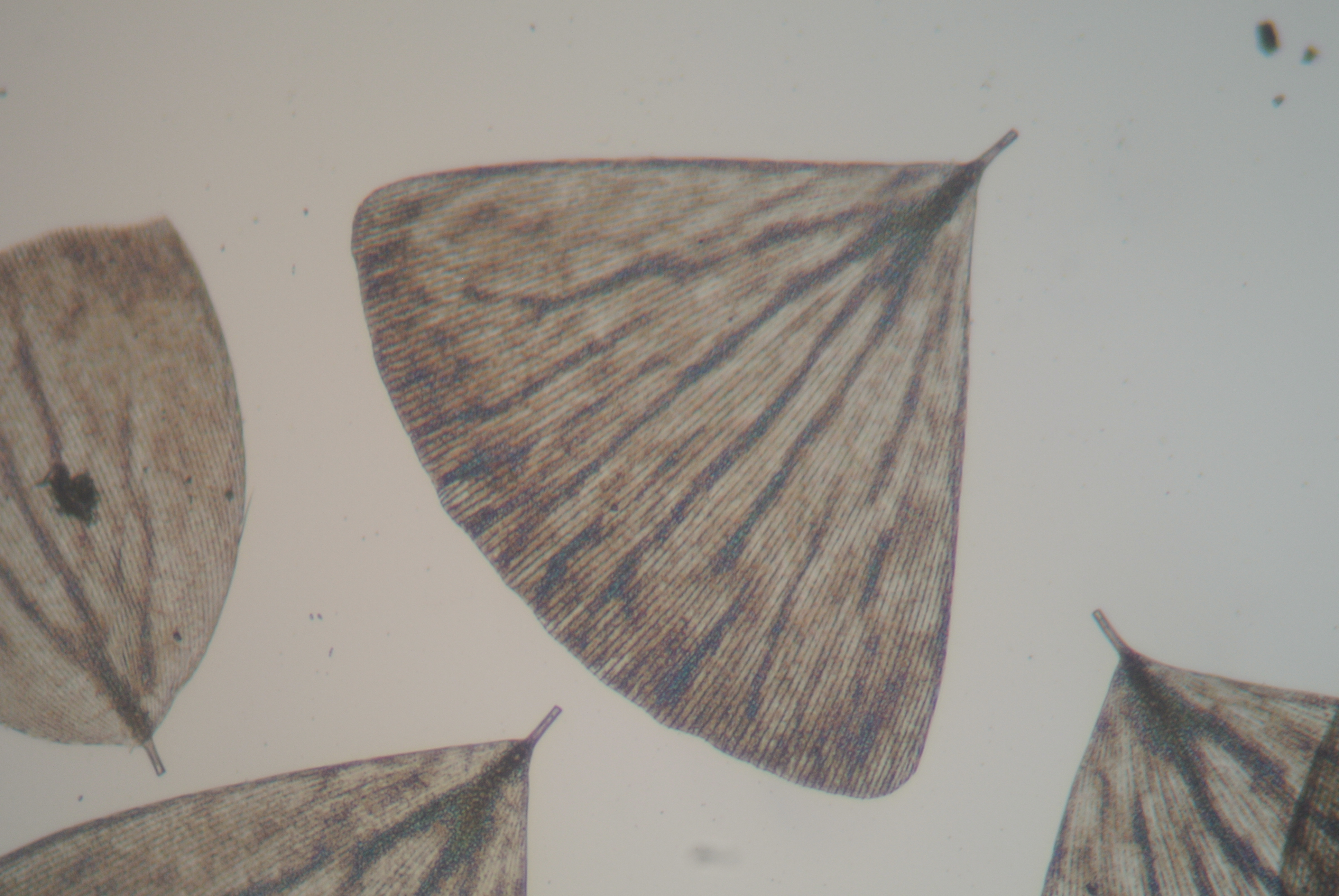
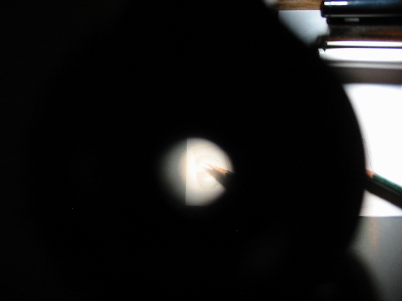
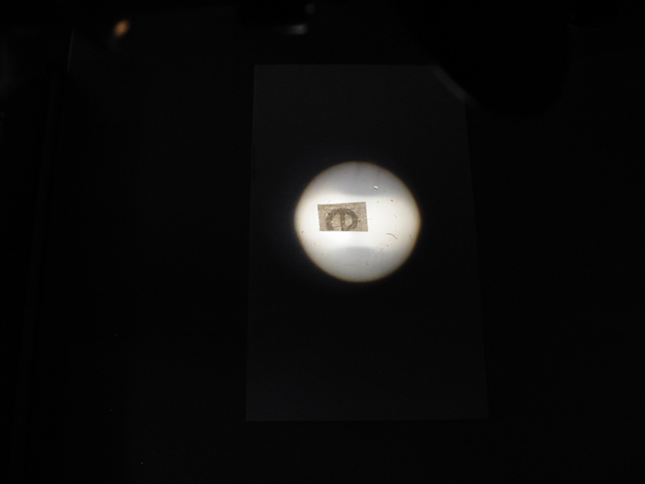
With an object in place (and in focus) it is the work of a moment to obtain a focused image of the iris of the illuminator using the condenser, and adjust the iris of the condenser to so that the numerical aperture of the condenser matches that of the objective for true Köhler illumination. The method of August Köhler to provide a field of light perfectly uniform and out of focus, while retaining all the characteristics required for maximum resolution are today recognized and accepted as optimum for advanced work. Köhler illumination puts a focused image of the light source (the filliament of the lamp or grain of a ground glass screen) at the iris diaphragm opening of the substage condenser and again at the back focal plane of the objective. A bright evenly lit field is then formed at the iris diaphragm opening of the illuminator and in the image plane of the focused microscope slide.

In the photograph the illuminators iris diaphragm has been stopped down well beyond what would be used in practice to better show the in focus diaphragm simultaneous with the image plane of the specimen. Note that despite the light source being a ground glass there is no visible grain in the photomicrograph.

Critical Illumination with the AO Fifty

IMG_1658rotatecropedit
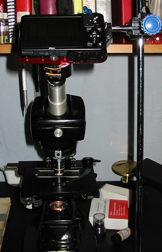
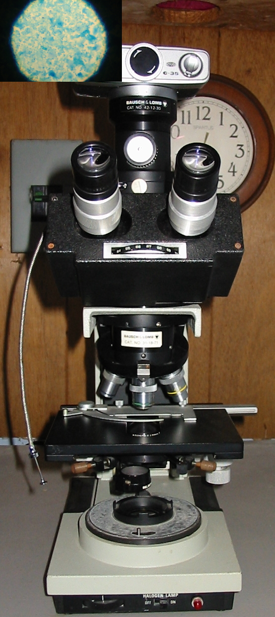
This American Optical Fifty series microscope makes use of an uncomplicated 15watt (medium base) incandescent bulb as the light source. Mounted in an adjustable housing in the microscopes base the light of the bulb is sent first through a blue filter. Immediately above the filter is mounted a single short focus Plano-convex lens with a ground glass flat surface. This arrangement makes up the integrated illuminator common to microscopes of the Fifty, Sixty, One-Fifty, and One-Sixty series. Above the field lens of the illuminator is a 1.25N.A. Abbe condenser on rack and pinion adjustment.

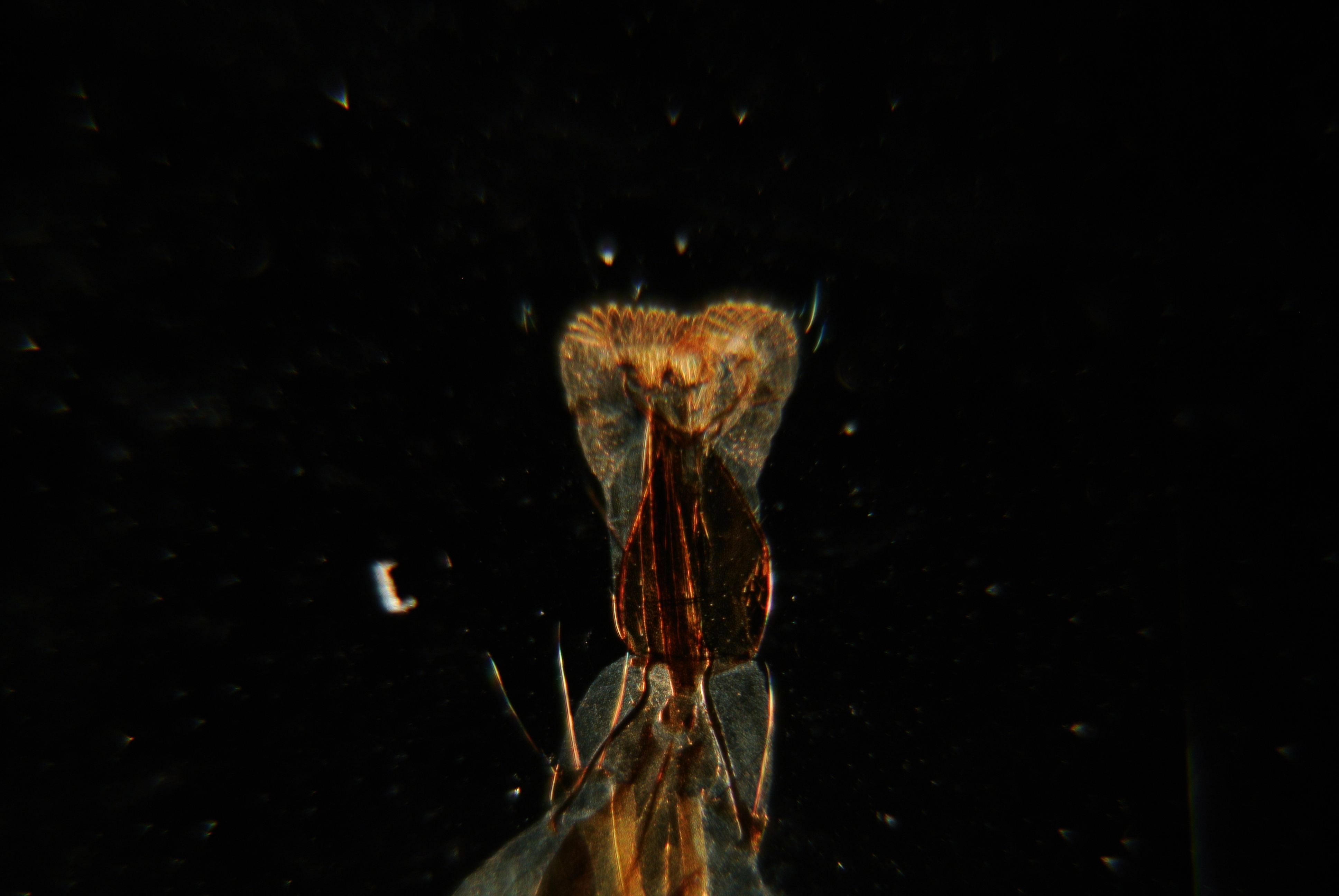
With this setup Köhler illumination is not possible. Instead a less perfect but far less mechanically demanding type of illumination known as critical illumination is possible. Prior to the modern acceptance of Köhler illumination as the gold standard it was practice to work with a large light source and less complex illumination apparatus. Rather than a focused image of the light source, a brightly lit field is formed at the opening of the substage iris diaphragm and the back focal plane of the objective. Unfortunately, this results in a focused image of the light source (and all its attendant grain or irregularities) being formed in the image plane of the specimen. The worker is then apt to throw the substage condenser slightly out of focus so as to avoid the distracting image of the filament when not using a sufficiently large homogeneous light source.

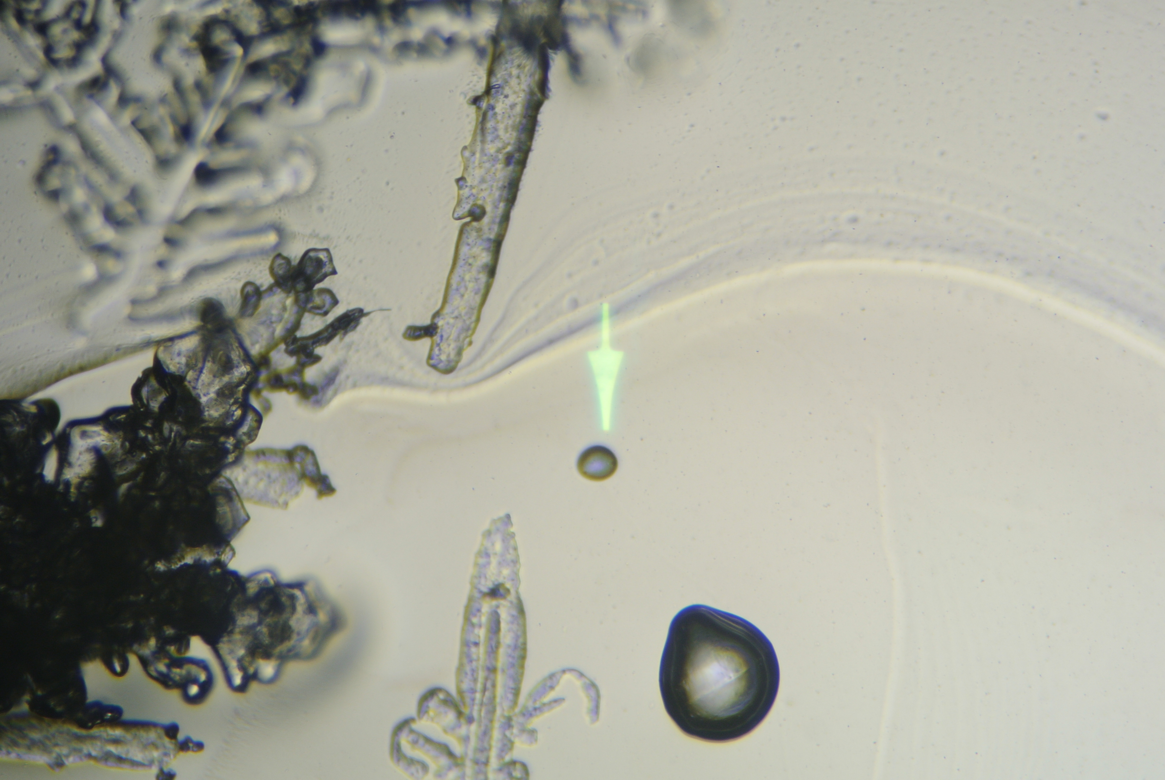
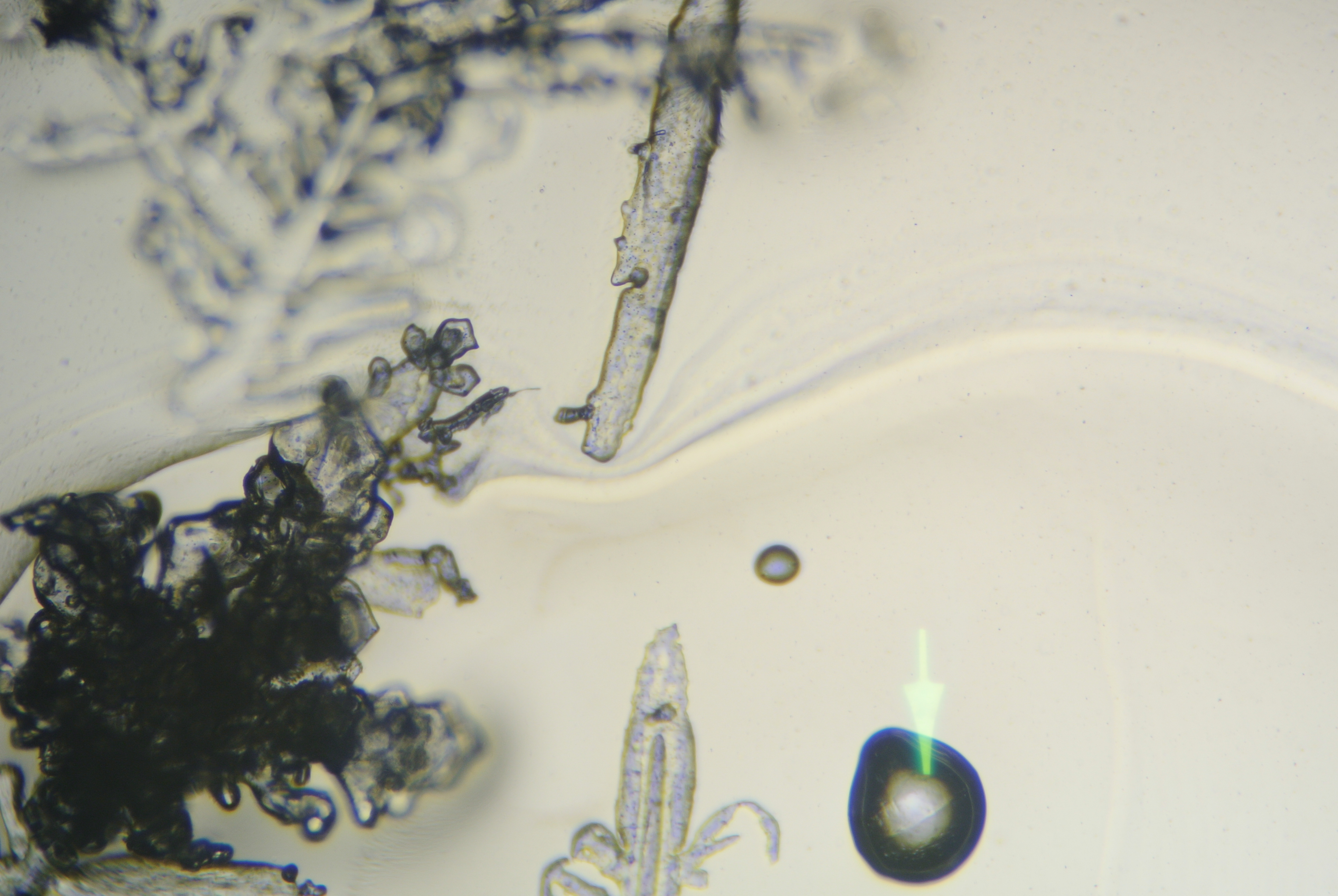
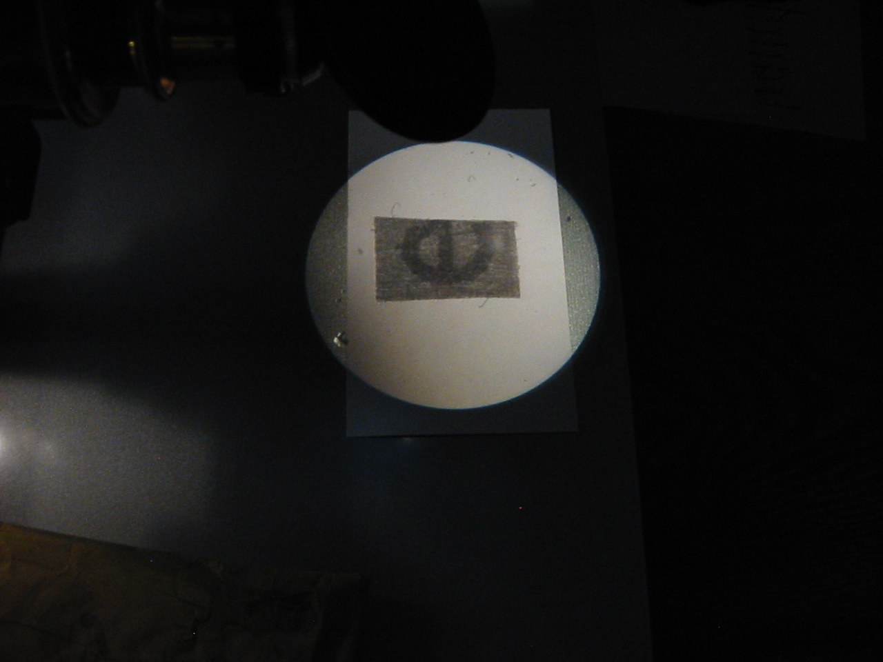
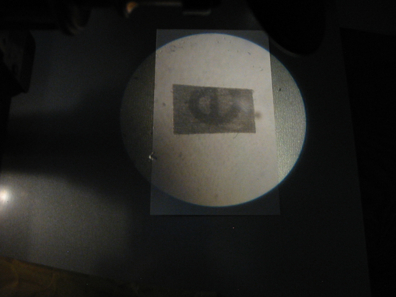
Not that in the upper photomicrograph there is evidence of dust on the ground glass illuminator, as shown by dark areas indicated by the pointer. In the lower photomicrograph the substage condenser has been thrown slightly out of focus to prevent grain and dust from appearing in the image plane of the specimen. In general use one may chose to rack the condenser up or down if the grain of the illuminator is found distracting, there is however a slight increase in spherical aberration and decrease in resolution.

Add-on Integrated Illumination

IMG_1657cropedit
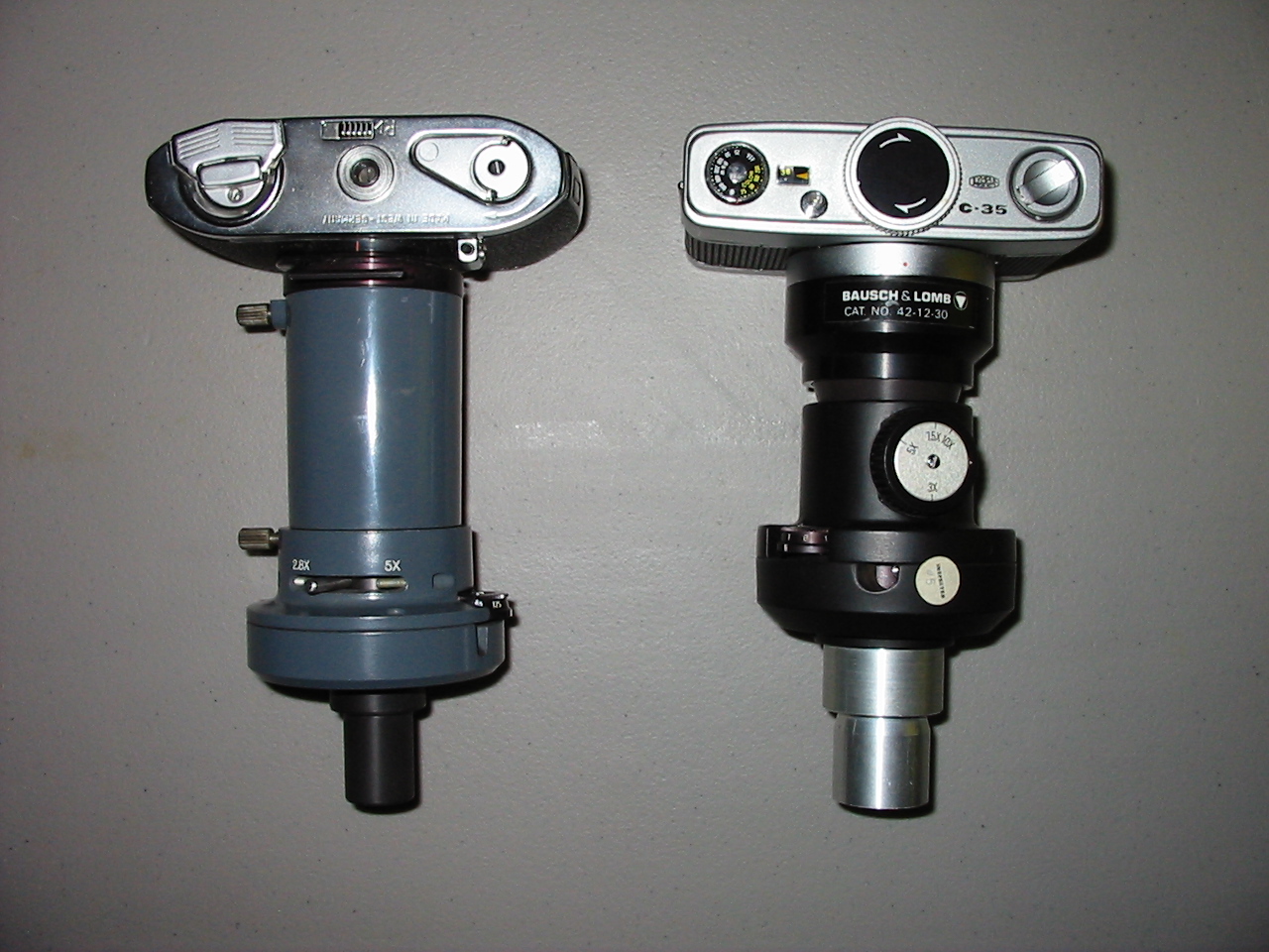
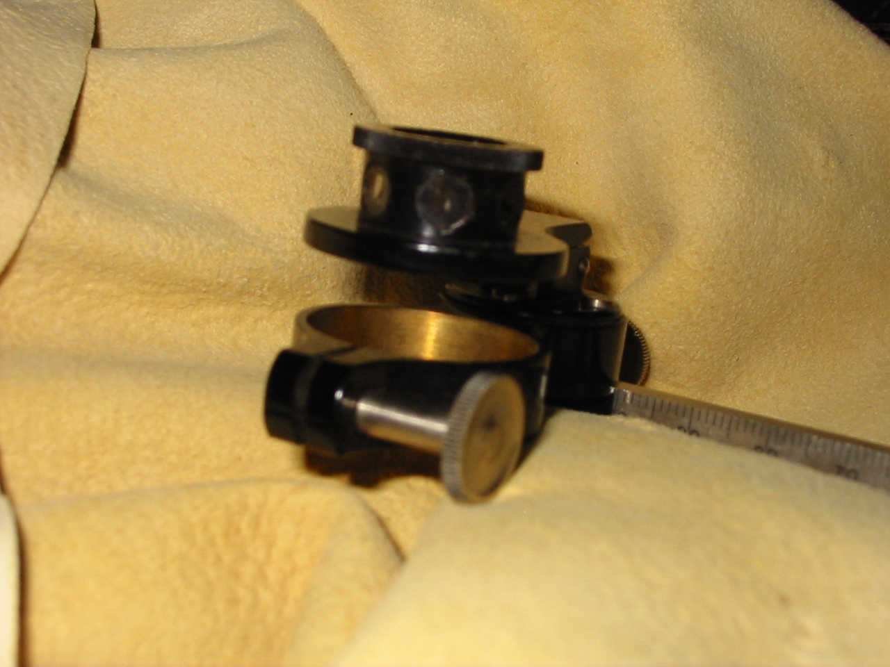
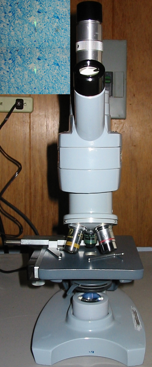
Largely as a response to the need for simplicity and convenience when introducing microscopy to students, a large number of manufacturers began to sell small self-contained light sources in the mid-twentieth century. These simple lamps could be used in the conventional way with a mirror bearing microscope by sitting the lamp upon the table, or by mounting it directly to the base of the microscope. The Bausch & Lomb lamp shown here was available with two different mounting brackets; one which made use of the mirrors mount, and that pictured which would be fit over the removable substage iris diaphragm before it was screwed back into the base of the substage condenser.

This illuminator consists of a small 15watt (medium base) incandescent bulb in a switched, sturdy, Bakelite shell. Over the bulb is mounted a blue glass filter with one ground glass surface, followed by a Plano-convex lens. The exposed convex surface of the lens is ground as well. Depending on the arrangement in which the illuminator is used, one can work with critical illumination or not, but again Köhler illumination is not possible.

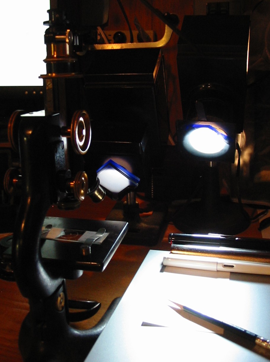
Such lamps are chiefly recommended by their simplicity, durability, and availability at low cost. Less often mentioned is the versatility of such lamps. Any illuminator of this sort§ may be arranged to provide ample light in most circumstances a beginning microscopist is likely to encounter. It may be used with or without a substage condenser, or even without the mirror; as it may be set on the table between the foot of the microscope with the light projecting upwards through the stage. If such a light source is to be used it should be considered a component of the microscope, and kept with it at all times.

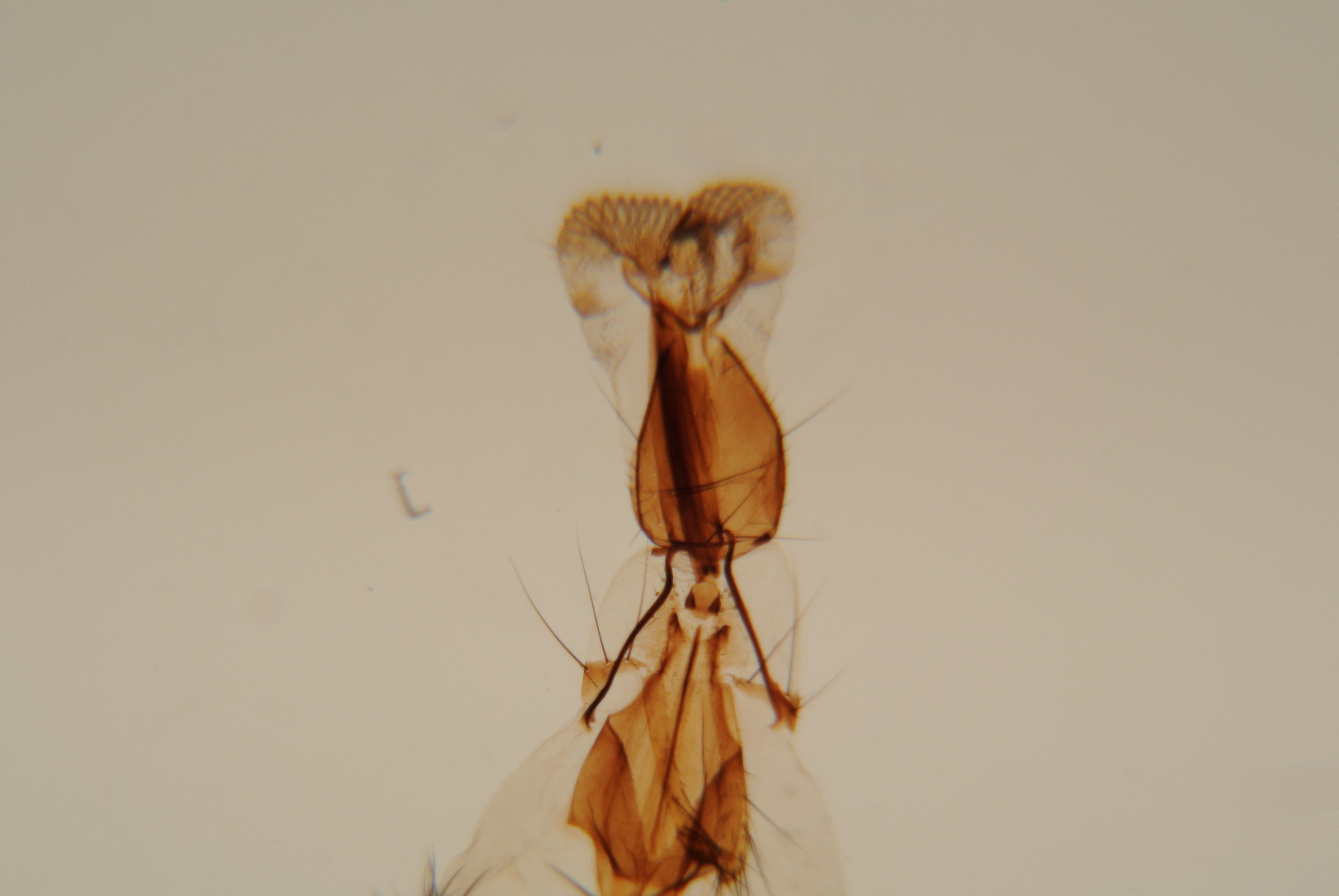
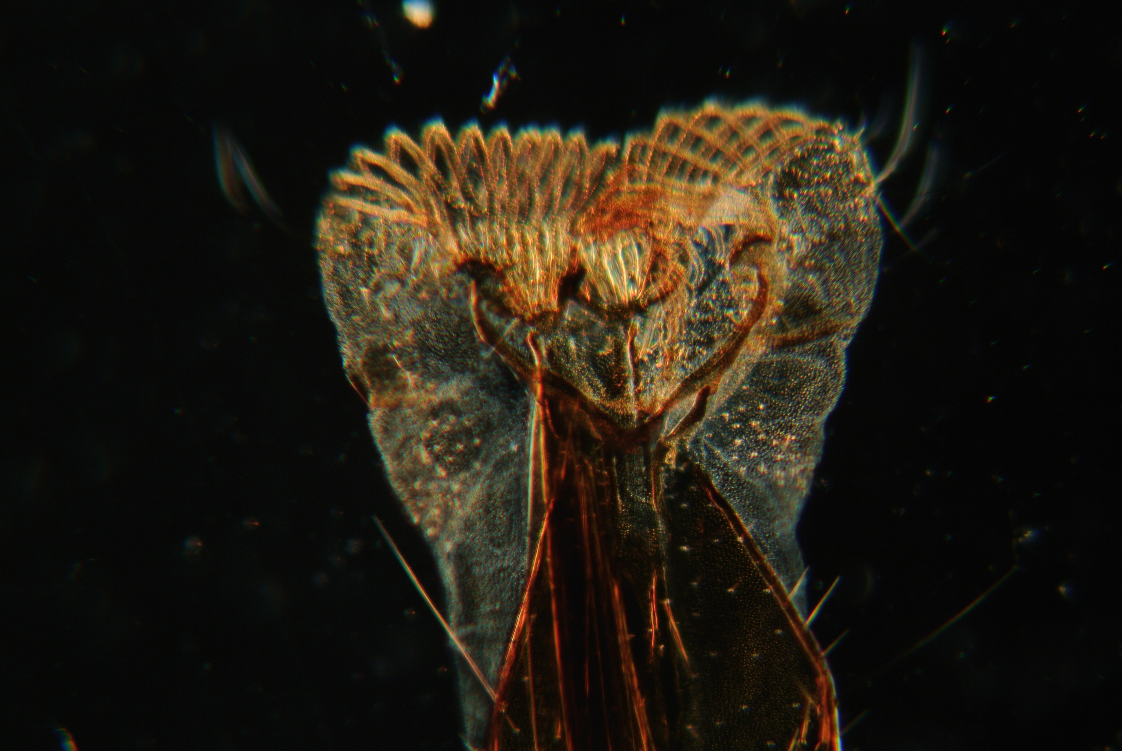
In the upper photomicrograph the lamp was placed on its back below the substage. Although the illumination is not critical the central portion of the field is even lit and free of grain. In the lower photomicrograph the lamp was positioned ten inches from vertical axis of the microscope and its light reflected by the plane mirror. With the surface of the ground glass focused critical illumination resolves the center of the field of view with slightly less spherical abbaration, although grain is once more introduced into the image and it is evident that this author did not take time to properly center the lamp.

Notes:

∗Well into the twentieth century arguments continued to be raised as to the technical or practical superiority of the various methods of specimen illumination. One may at first wonder at the controversy but it seems to have largely resulted from the need for more specialized light sources with Köhler illumination and the practicality of critical illumination when used with any large (flame or cloud for example) light source. The past popularity of point light sources is a product of the growing pains of the adoption of Köhler illumination as it was generally felt that a bright point of light provided more capacity for filtering without diminishing intensity.

†Technically, in critical illumination that brightly lit filed is formed just before the back focal plane of the objective and moves closer towards it as the power of the objective is increased.

‡Obviously with the lamp mounted directly to the substage condenser one can not bring the ground glass surface into focus in the specimen image plane as is required for critical illumination. Working with the lamp on the work table, or with the lamp mounted to the mirror bracket it may be brought into focus with the substage condenser if it is in range of the primary focus. I am uncertain as to why B&L would grind the convex surface of the lens, but I suspect it was motivated more by the desire to make the device less open to damage by unskilled hands (there are no exposed polished lenses to worry about) than by optical concerns.

§All of the major manufacturing houses put out similar lamps with differing arrangements as to bulb and glass. A popular American Optical model was equipped with a blue filter and swing out ground glass or bullseye lens, providing a limited means of controlling the intensity of the light. Modern LED or incandescent lamp housings are available that will mount in place of the double sided mirror of most vintage stands, one need only verify that the mounting is compatible.

If things seem complicated don’t wait on the availability of fancy equipment, great work has been done with desk lamps and white clouds. Next time we’ll look to external illuminators. -K

What Happened to Spring?

Here we are enjoying the second week of the spring season and yet again, it’s snowing. -K

Spring is easily among the most productive seasons for the nature microscopist. Freshwater diatoms are at their peak in the spring, and many insects that have overwintered are out, as are the various forms that hatch as the weather warms. If there is a body of water a convenient distance from ones base, it can be very educational to chart the rise of spring by each day doing a quick survey of the contents of a drop of water. Does the density and variety of microbes rise steadily with temperature? Does it fall or continue to rise as snow-melt dilutes the body of water with a seasonal influx? Or does it just keep snowing!

Note the artifacts around the arrow.

Note the artifacts around the arrow.

Above is an image taken of a preserved snowflake. It is not a very good preparation but illustrates a couple points that should be emphasized. Firstly a bit of information on the preparation itself. Snow was allowed to fall on a clean slip and over a likely specimen was dropped a solution of polyvinyl formal. Without the addition of a cover glass it was maintained at a freezing temperature for a few minutes as the resin formed a cast of the captured ice crystals in a gas permeable clear plastic. When brought indoors the water from the ice crystals was able to evaporate leaving a hollow shell that may be observed.

At the tip of the arrow we observe a large air bubble. As a result of the method of preparation the air bubble formed because of air trapped in the resin itself. The large size of the air bubble makes its identity obvious and more of a nuisance than a distraction. To the left of the arrow we see an additional bubble much smaller in size. Such bubbles will spoil any preparation but illustrate an important lesson concerning depth of focus and optical alignment very well.

In the above image the small air bubble presents with a distinct black outline. This black outline is too large to illustrate diffraction rings well, but that is the principal behind much of the following. The black portion is caused by stacked layers of out of focus image planes. As a result of the known shape (spherical, with some distortion) of air bubbles we can easily picture it in cross section, the optics of out microscope can not however provide a clear outline of the section because the layers above or below obscure the image.

The top aspect of the bubble in focus.

The top aspect of the bubble in focus.

Increasing the magnification we can easily bring the top aspect of the bubble into focus. The black outline then becomes an aid in determining the actual form of the bubble. If our lighting is truly central we are able to discern that the portion of the bubble nearest the pointer is thicker than that which is farther away, as evidenced by the more pronounced black fringe.

If our lighting is not central then we can use the bubble to determine in which direction to move our condenser to bring it into alignment. In the above example we might take the lighting as generally central, which we can tell by observing the black fringes on the larger air bubble. However, to be truly accurate we can observe that there is a very light fringe just inside one edge of the larger bubble. Adjusting the condenser a very minor amount in the direction opposite that fringe we are able to obtain more perfectly aligned illumination.

Our condenser properly aligned provides axial lighting.

Our condenser properly aligned provides axial lighting.

Although still not entirely axial we observe that the fringe is much less in evidence. Properly aligned illumination is vital to correct interpretation of the image. We can now form a more accurate mental image of any object we elect to observe simply by sending the fine focus just above or below the image plane we wish to observe. Axial lighting provides that any dark fringes we observe will be a product of the specimen rather than an artifact of our illuminating system.

Digital Photomicrography with the Student Microscope

I can not stress enough the importance of traditional micrography as a means of gaining understanding of the specimen, but for ooh and ahh factor digital is king. -K

The setup

For digital photomicrography a consumer grade mirror-less digital camera with removable lens is mounted over the eyepiece with a two part connector. The first part fits into the cameras lens socket and is friction fit to the second part which fits over the microscopes tube and rests upon its shoulder. The camera may be removed at any time without difficulty and all apparatus is away from the ocular so that it is un-obstructed and may be changed. With the camera removed the microscope may be focused as normal without recourse to the cameras display. As the imaging sensor is at the microscopes eyepoint no secondary focusing is required when the camera is moved into place.

The microscope is that same common workhorse that has been featured in the previous entries. Lighting is provided by a single 60 watt cool-white incandescent bulb in a goose-neck desk lamp. A 5x Huygenian ocular is used for every image. The camera is an older Nikon 1 J1. Anyone desiring to know the settings used for each exposure is advised to check EXIF data for each image. A traditional test object, the proboscis of a blow fly, is used for each image. Be warned, clicking on the images will display a full size (3872×2592) image of several megabytes size.

Photomicrographs

First we remove the lower portion of the divisible 10x objective leaving a perfectly serviceable 32mm equivalent focus objective. A larger aperture opening is spun into place with the circular diaphragm to avoid vignetting the image.

DSC_0628Not bad considering the aberration inherent in such a lens. Observe that despite being relatively close to the center of the field of view the finer points of tung are out of focus.

***

With the assembled 10x divisible objective (16mm EF 0.25NA) spherical aberration in particular is much less obvious. A smaller opening of the circular diaphragm is selected to provide better contrast and reduce glare. No realignment of the concave mirror was made.

DSC_0638Much more of the structure of the tung may be made out although the depth of field is noticeably lacking. Only the smallest evidence of chromatic aberration is visible. Despite what is a very rudimentary lighting system the field is bright and even.

***

Switching to the 43x (4mm EF 0.65NA) objective we switch also to the smallest available aperture in our circular diaphragm. Unlike the previous change in magnification using the divisible objective the change from 10x to 43x is relatively parfocal and a few turn of the fine focus results in the following image.

DSC_0643The field is surprisingly well lit for the absence of a condenser. One may observe that depth of field is more than one might expect especially when considering the relative thickness of the specimen. The color fringes of chromatic aberration are in evidence and anyone accustomed or intending to do much work at this magnification would surely be unsatisfied with the image. Understandably, one with experience might forget that those relatively new to the pursuit are less sensitive to such things and would likely be rather happy with the quality of the above image.

***

Turning the arm of the mirror sharply to one side and switching to the largest opening of the circular diaphragm we are able to take advantage of an all but forgotten lighting technique. A shade is placed so that the area below the diaphragm opening rests in shadow and the lower portion of the divisible 10x objective is removed.

DSC_0650Oblique lighting is not generally possible with a substage condenser. Specialized stops may be put into place but even then the obliqueness of the light is subject certain limitations relating to the working distance and numerical aperture of the condenser. Here a starkly black background is visible because the surface of the table is black and out of focus for the objective. The specimen is brightly lit by the mirror and that light which it sends into the objective. Every speck of dust on the slide is noticeable and in the full size image one has no trouble at all in identifying to which side the mirror was swung (to the left).

***

With the fully assembled 10x objective a passable image is produced which is serviceable as a “poor mans dark-field”. Patch stops intended to render a standard condenser a dark-field substitute do not provide so dark a background.

DSC_0649

Box Camera Photomicrography

Don’t follow my advice on developing, I know microscopes; not photography. -K

Of all the books on photomicrography perhaps the most in depth is that written by Dr. Roy M. Allen. As technical as it is the book is not without its own charm. Buried in a footnote, Dr. Allen relates his first attempt at photomicrography as a child in the late 19th century. He made his images with a box camera, using the sun for illumination.

Having a box camera on hand, I thought I might give the process a try. The camera is an Agfa Ansco Shur-Shot B2 manufactured a few towns over from me in Binghamton, New York back in the 1930’s. It’s a wonderful camera for this, shooting widely available 120 film and featuring a shutter that provides for both short (approximately 1/50th) and long (B style) exposures. Unfortunately, the cameras lens is a hyperfocal meniscus lens that is less than optimum for photomicrography. A quick examination showed that the lens was held in by a simple tension ring and could be easily removed without causing any damage.

Using a lab jack made elevating the camera to the microscopes eyepiece very simple, though a stack of books could do just as well. A bright illuminator (a halogen lamp by B&L) that dates to the same period as the microscope and the camera, rounds out the setup. By using such a bright illuminator I hoped to keep the exposures short and avoid the vibration of operating a manual shutter.

The low power magnification didn't require a condensor so a stand with a simple disc substage was used.

The low power magnification didn’t require a condenser so a stand with a simple disc substage was used.

The depth of the box is less than 147mm, so photo and projection eyepieces are out, and a standard 5x Huygenian eyepiece was used. Thankfully, spherical aberration was less than I might have expected using achromatic objectives and a bellows length of less than 125mm. As box cameras have ground-glass view finders that are independent of the lens, (the two circular lenses seen on the right of the camera above) focusing can not be done through the camera once film is loaded. Prior to loading one may hold a paper or ground glass at the rear of the camera to determine the size of the image formed. A simple paper tube covered at one end and having a length equal to the distance from the cameras shutter to the film, serves as a focusing screen. Exposures are made by focusing with the tube and then replacing it with the camera and depressing the shutter.

An image as seen though the focusing tube.

An image as seen though the focusing tube.

With the film loaded into the camera and the intended slides at hand it is only a few minutes before I have a roll of B&W 120 film ready for developing.

After loading the film onto a reel and placing it into a developing tank in a changing bag, I processed it for 15 minutes with Pyro-Metol Kodalk followed by a plain water stop bath. Next the developer was poured into a beaker and the fixer went into the tank for six minutes. I used an alkali rapid fixer known as TF-4. Following the fixer, the film (now safe to expose to light) went into the used developer for two minutes prior to a 30 minutes wash.

Presto! A roll of 8 photomicrographic negatives having the classic circular aspect and clarity of medium format. Each negative image measures 45mm in diameter. All in all, the results seem rather nice considering the film I used was some Kodak T-Max 100 that expired back in the mid 1980’s and came to me via eBay for just a few dollars.

The question now is whether to get a negative scanner or a darkroom for making prints.

The digital photo does not do the clarity of this negative justice.

The digital photo does not do the clarity of this negative justice.

Elucidating Integral-lens photomicrographs

Preventing Obscurity

Once a photomicrograph is produced, one may desire to know some basic information regarding it; for example the scale of reproduction, or degree of magnification. To calculate most information only a little simple math is required. The formula for determining the scale of reproduction when using a camera with an integral-lens as follows:

Scale of reproduction = Objective magnification x Eyepiece magnification x Focal length of lens / 250

The formula works because the product of objective and eyepiece provides the initial base magnification, while the second portion of the equation provides the degree of reduction effected by the cameras optics. The lens will provide some level of reduction, unless it has a focal length equal to or greater than 250mm, which is expressed as the quotient of its focal length (in millimeters) and 250. The divisor in this case comes from the distance at which the virtual image is produced by the microscope expressed in millimeters.

The authors lens has a fixed focal length of 55mm, (which will provide a reduction of approximately 1/5) meaning that a 10x objective and ocular will produce a photomicrograph presenting with a magnification of 22x. To determine the accuracy of the calculation [or when using cameras with lenses of unknown focal length] one may measure the field of view visually with a stage micrometer (in this case measured at 150μ), and again as reproduced on the photomicrograph (measured at 63μ) and calculate the practical factor of reduction or effective magnification of the photomicrograph (23x which bears out the accuracy of the previous calculation).

Many consumer digital camera carry a lens with a variable focal length of from 2-25mm and this may be set by the user in manual mode, or determined after the fact by reading the exif data of the digital image.

For most focal lengths one will discover that the entire photosensitive surface is filled, be it 35mm film or a digital sensor. As a result only a portion of the microscopes field of view will be recorded. This effect will surprise some technicians who may expect to capture photomicrographs that are circular, just as the field of view is. Theoretically, to capture a more complete image of the field of view presented by the eyepiece, one may employ a lens having a shorter focal length. To determine the lens focal length that will provide the ability to capture the entire field of view one must know the nominal size of the field of view provided by the microscope eyepiece in use as well as the size of the imaging surface.

The rectangular sensor of the authors Nikon 1 J1 digital camera is 13.2mm by 8.8mm giving it a hypotenuse of 15.8mm. To entirely fill the sensor area, and produce a rectangular photomicrograph, while still imaging the largest portion of the field one will use the sensors longest dimension in the following formula. To image the majority of the field use the smallest dimension. The field of view index may be determined in a general way by measuring the field diaphragm of the ocular employed, it may be inscribed on modern oculars as a number following the inscribed power.

The imaged areas hypotenuse is equal to the sensors hypotenuse divided by the index of the field of view provided by the eyepiece.

Sensor dimension / Field of view index = Visible image diameter

This equation should well illustrate that a significant change in the scale of reproduction as effected by the cameras lens, will in essence, spread the photosensitive surface over a larger portion of the field of view. Doing so, will serve to reduce the resolution of the photomicrograph. So it is best then to use the above equation only to describe the power of magnification inherent in the image. With the above information one may mark a photomicrograph with a line and appropriately label its length with ease. Micrographs are best provided with this marking as it then acurately provides information on the size of imaged structures and magnification independent of the size at which the image is produced as a print.

Suffice to say that if one desires to image the whole of the visual field without introducing significant aberration or image degradation the simplest and best method is to operate a camera with a very large photosensitive area. One may consider that most of the historic photomicrographs (especially those presenting a circular field) were produced on plates or films considerably larger than 2.25 by 3.25 inches which is quite a bit larger than most widely available film or digital sensors.

What is the take away from all of this? Consider alternatives to the use of an integral-lens camera if one needs to produce an image having particular magnification or field coverage. Use the above to determine the characteristics of the photomicrographs one does produce and strive to take superior images with the equipment one possesses.

Photomicrography with Integral-lens Cameras

Don’t forget to renew (or begin) your membership in the Royal Microscopical Society before the 31st to ensure an uninterrupted full-year of membership. -K

Many of the primary faults of compromise photomicrography can be eliminated by simple means. Various apparatus may be purchased or crafted that contribute to success, and because of the ingenuity of microscopists the apparatus will not be expounded in any detail. Instead, the topic will be methods of producing optimum images when using a consumer grade digital or film camera which has a lens, but first permit an explanation of the chief faults of the method: vignetting, and obscurity.

A vignetted image is caused by the obstruction of a portion of the image by an aperture. The aperture may be within the cameras lens, the microscopes ocular, the body tube, or even condenser of the microscope. Most vignetting may be eliminated by ensuring the camera (and its lens) are aligned with the optical axis of the microscope, and the remainder by setting the lens of the camera properly as regards focus and the size of its aperture.

By obscurity one means the lack of precision regarding the photomicrographers knowledge of the image captured. When using a commercial apparatus one is aware of many things regarding the image because the manufacturer provides that information. When using a compromise apparatus one may be at a loss in determining the scale of the photomicrograph or even its degree of magnification, for example.

Preventing Vignetting

For optimum results one must position the camera so that the lens takes the place that would be occupied in normal operation by the eye of the microscopist. This means that not only should the camera share an optical axis with the microscope but that the initial optical component of the lens must be placed at the eye-point (exit pupil) of the microscopes ocular. In normal visual operation one finds this point instinctively by simply moving their head until the best image is observed by the eye. For photomicrographic use one may find the position of the exit pupil by holding a piece of index card over the eyepiece of the focused microscope. Move the card towards or away from eyepiece until the point of light seen on the card is smallest and then measure the height of the card over the eyepiece. The writers 10x B&L ocular produces its exit pupil at 5mm.

In operation a camera is focused on an object based on the distance of that object from the camera. In photomicrography, the object photographed is at a constant and known distance regardless of the ocular or objective in use. By design this distance is that of the eye at relaxed focus on an object as seen at 25cm (or 10 inches) distant-relaxed focus of the eye being equivalent to an optical system focused at infinity. Hence the oft made admonition that one should look through the microscope with eyes relaxed, rather than into the microscope with eyes strained. As such one should place an auto-focus camera in manual and set the focus to infinity (100feet or 30.5meters on some cameras). A manual focus lens should be set at infinity as well.

If the lens of the camera is then placed at the exit pupil of the focused microscope, no additional focusing of the microscope should be necessary to produce a sharp photomicrograph. This is particularly relevant if one is using a film camera (or digital camera without an LCD) as the cameras prism is unlikely to prove operational in this context. It is also relevant as the display of a digital camera will generally lack the resolution to ensure sharp focus. Following the above recommendation some microscopists may discover that they are in the habit of accommodating their vision for different focal distances when using the microscope. Young individuals in particular are likely to find this condition and can determine the degree of accommodation by focusing the microscope and then manipulating the focus of the cameras lens until a sharp photomicrograph is produced. A similar situation is apt to be experienced by those who wear eye-glasses and are in the habit of removing them when operating the microscope-one may discover if this is the case by focusing with eye-glasses on and then observing the sharpness of the image with eye-glasses removed.

Following the above methods, one is unlikely to experience vignetting. If it is still observed and can not be eliminated by altering the alignment of the camera to the microscope, it is apt to be attributable to the size of the camera lenses aperture. One must ensure that the camera lenses aperture is equal in size to, or larger than, the exit pupil produced by the ocular employed. With film cameras one should always employ the largest aperture opening available both to eliminate vignetting and to ensure that the image captured on film is illuminated consistently and does not dim towards the borders of the field of view.

This is getting rather long so eliminating some of the unknowns inherent in compromise photomicrography will be discussed in the next post. -K

Compromise photomicrography

There is no reason to run out and buy anything, for the below I used only what was already on hand. -K

Provided one has a microscope and a camera, no additional equipment is absolutely required. In a pinch a photomicrograph may be produced by holding it to the eyepiece and hoping for the best. Some simple steps may be taken to ensure the best possible result of this slipshod technique. The chief argument against holding a camera to the eyepiece is that the stability of ones hands is not so reliable as one might prefer. Overcoming this difficulty is not so complex as it may first seem.

The microscopists eye replaced with a consumer grade 35mm camera.

The microscopists eye replaced with a consumer grade 35mm camera.

In a slim text titled Photomicrography put out by the Eastman Kodak Company an excellent method of positioning a camera at the eyepiece is illustrated. In the text it is recommended that one fabricate a simple wooden board with an appropriately sized hole to accommodate the lens of ones camera. Once placed through the board the body of the camera is held firmly in place by rubber bands. The whole is then suspended over the microscope on a standard laboratory ring stand so that the lens of the camera corresponds with the eye-point of the objective.

Once the microscope is focused normally, the camera may be swung into position. On some varieties of camera the regular sight would then be used to verify focus, or a ground glass focusing plate might be substituted for the regular camera back. The large digital displays of modern cameras provide an added convenience when it comes to focusing, and widely available software for tethered camera control as well as wireless remotes eliminate the risk of misalignment during exposure. Additionally, the absence of any mechanical shutter eliminates a common source of vibration which was the bane of many an amateur photomicrographer.

With a ring stand it was the work of a moment to position a camera over the eyepiece of a microscope oriented fully vertical. If one did not have a ring stand or similar support on hand, one might easily utilize a standard photographic tripod towards the same end. Adapting the method for use with a microscope with a permanently inclined eyepiece (such as the B&L Dynoptic, pictured below right) required no more effort than trading the ring support for a utility clamp mounted on an intermediate boss-head.

Vertical microscope with ring supported digital camera.

Vertical microscope with ring supported digital camera.

Considering briefly, one might see how this same general method could be adapted for use by an individual possessed of nothing but a standard microscope and camera. Manipulating the microscope so that it is fully horizontal permits simply sitting ones camera on any convenient support that will elevate it to the height of the eyepiece.

Fixed angle microscope with camera held at apropriate angle.

Fixed angle microscope with camera held at appropriate angle.

Presently, all manner of custom mounts and accessories have been manufactured and marketed to the amateur that simplify arranging and aligning photographic apparatus-from cellular phones to expensive DSLR’s-at the eyepiece of any optical equipment from microscope to telescope. Such equipment is largely unnecessary as has been demonstrated above.

But are the images produced by this method acceptable? Without specialized equipment or complex software the below image was produced. In all it took longer to walk to the shelf on which the ring stand was stored than it did to arrange the equipment and take the photomicrograph. In the image below one can see that ample room for improvement exist. Having lately been playing around with an old Russian range-finder lens which was mounted to a Nikon 1 J1 body, it was the camera used. Looking at the lens afterwards I note that it was focused to about 10.5 meters and the aperture was fully open. In any case below is the image produced of a traditional test object for low powers, the scales of a butterfly, as seen with a 10x objective and 10x ocular.

Be warned the full size image is ~4MB.

Be warned the full size image is ~4MB.

In the next post methods of achieving optimum image formation with the above method will be discussed.

Cameras!

Photography is as allied with microscopy as could be, so do forgive this. -K

There was a time when possession of a microscope was a rare and novel thing. However rare it may be, it is certainly no longer novel. The same might have once been said of the photographic camera, but in the present day it might be more rare to encounter one who does not possess a camera. With the proliferation of cellular smart-phones it may seem that everyone is in constant possession of camera. This situation is apt to elicit a particular behavior; the placement of a camera at the eyepiece of a microscope.

Initially existing photographic apparatus was adapted to the microscope by the operator to meet their individual tastes and needs. Before long, manufacturers began putting out specialty photographic apparatus intended to be placed at the eyepiece of the microscope. Sometime later specialty microscopic apparatus-possessed of a beam splitter and photo tube-that required even more specialized photographic apparatus became the standard, below are two 35mm cameras of that sort.

Two varieties of integrated photomicrographic apparatus.

Two varieties of integrated photomicrographic apparatus.

Simple, and easy to use, versatile cameras like the above provide variable levels of tertiary magnification. Shutters are integrated and fittings for remote shutter release are provided, along with connections for automated exposure meters, and on some models other computerized accessories. Unfortunately, these sorts of camera are very non-standardized. One might notice that the lower optical connection on the above are of significantly different size, neither compatible with any of the standard eyepiece diameters. Apparatus of this type is only suited for use with microscopes equipped with a photographic head, and even then one can not be certain of physical-never mind optical-compatibility.

Modern stands equipped with photographic apparatus are frequently of questionable quality and universally expensive. Vintage stands tend to be incomplete and similarly expensive. Unless one is lucky or particularly knowledgeable this sort of apparatus is best pursued only cautiously. Instead, one might take a page from the microscopists of years ago and seek to adapt standard photographic apparatus to photomicrographic work.

The next few posts will treat with this topic with a goal of producing professional quality photomicrogaphs conveniently and usefully. If this goal may be reached economically in a manner that provides optically superior results it is only because of the countless microscopists who labored with cumbersome tools and complex arrangements  to provide our understanding of the required techniques.

The Camera Lucida

Lets toss this off quick and move on to something else… -K

The camera lucida is a sort of artistic crutch which relies on the dedication of its adherents for its success. To be sure one can enjoy incredible results with the camera lucida, but the requirements of its use coupled with the complexity and expense of the device are sufficient that for casual micrography one is better off with other methods. For the individual with the rigid dedication to acquire skill with the camera lucida it is a tool of wonderful capability, for nearly everyone else it’s a device of torture.

The principle on which the camera lucida operates is reflection. Whereas in the previous post an image of the specimen was reflected onto the drawing surface, here an image of the drawing surface is reflected into the eye as it simultaneously observes the specimen. Apparatus which achieves this has been adapted to all manner of situations and some schools of art teach the use of the camera lucida to artists as a method of perfecting perspective. For micrography the camera lucida seems to have fallen largely by the wayside, perhaps even more so than micrography in general. However, modern camera lucidas are still available and there are occasional adherients in professional and amateur microscopy who make regular use of vintage instruments.

Idealy one wishing to begin serious micrography with the camera lucida should purchase the apparatus. If however one wishes to get an idea of the use before making the expenditure a simple experiment can be made with nothing more than a coverglass. Incline the microscope so that the body is horizontal and position a coverglass at a forty-five degree angle over the eyepoint of the ocular. When aligned correctly and the specimen and area below the coverglass are illuminated just right one will see both when the eye is placed close above the coverglass.

Apparatus of this sort was manufactured for many years which consisted of little more than a coverglass (or neutral tint reflector) in a frame held to a circular fitting which would slip over the rim of the ocular. Professor Abbe improved on this design significantly (others did as well but Abbe’s apparatus is the most generally found) by replacing the simple reflector with a neutral tint reflector having a small hole in its center and cemented between two right angle prisms. Parallel with the plane of the reflector he placed a mirror which would reflect the image of the drawing surface onto the reflector. With the device over the eyepoint of the microscope ocular one could observe drawing surface and specimen as a single image while keeping the microscope inclined in the usual position.

Excepting skill, success with the camera lucida is largely a matter of alignment and lighting. Proper alignment is had by first ensuring that the position of the reflector is in the plane of the oculars eyepoint. If this condition is not met no description of the difficulty and aggravation written here will serve. Next one must position the microscope so that the drawing surface is in plane with the image provided by the eyepiece. In practice this is most easily achieved by keeping the microscope fully vertical and the drawing surface fully horizontal. If this is the case the mirror of the camera lucida may be positioned at a forty-degree angle. If one has a camera lucida with the mirror fixed at an angle other than forty-five degrees the drawing surface will have to be inclined to ensure that a ray of axial light is at a 90 degree angle with the drawing surface.

Once things are aligned lighting must be considered. Light the specimen well enough for clear vision, and the drawing surface well enough that it is not overpowered by the light of the specimen or overpowering of it in turn. The variation of the Abbe camera lucida by Bausch & Lomb pictured below bears a variable series of filters which may be turned into the path of light reflected into the eyepiece to afford some level of moderation. In practice it is often more expedient to simply reserve a variable intensity lamp for illuminating the drawing surface.

The upper portion with filters to limit light sent to the eyepiece reflector.

The upper portion with filters to limit light sent to the eyepiece reflector.

Below one can see that with the microscope fully vertical the mirror may be positioned at forty-five degrees and the drawing surface left horizontal without distortion of the drawing surface. This is not the most comfortable position for use but it is the simplest to set up. Two illuminators are visible in the photograph. That on the left is used exclusively to light the specimen and bears a frosted daylight glass and 0.3 neutral filter. The illuminator on the right is used only for lighting the drawing surface and bears a frosted daylight glass as well. The bulb in each case is a 75watt Mazda halogen spot lamp.

Abbe camera lucida by Bausch & Lomb circa 1920 arranged for use

Abbe camera lucida by Bausch & Lomb circa 1920 arranged for use

Looking into the camera lucida one is presented with an image of the specimen and anything that appears below the mirror. If the image of the drawing surface is too dimly lit it will be impossible to see the image of the pencil point and therefor impossible to trace the outlines of the specimen. One may find that with low powers it is often necessary to dim the light on the specimen and increase the light on the drawing surface. In the case of higher powers one will find the lighting needs reversed. With some varieties of camera lucida one must be certain to keep ones eye in the same position continuously until the micrograph is complete, otherwise the image seems to move about on the paper. With the Abbe camera lucida one may move the eye as the image can only be clearly observed when it is above the hole in the reflector.

Below is something of the image one sees while looking into the camera lucida. At the right one can see a portion of the pencil while to the left one can see the reflection of that pencil simultaneous to the image of the letter “e” slide. The lighter central portion of the image in the eyepiece is not visible in use but is caused by the borders of the hole in the reflector.

Looking into the eyepiece

Looking into the eyepiece

Some time I shall have to make more of my efforts with the camera lucida fit to read of. Maybe put up some of the little things it permits one to do into words, but for now the camera lucida is rather more trouble than it is worth. Without an inclined drawing table it is uncomfortable in use and provides generally inferior results as it does not encourage one to spend any time improving ones skill.

Projection Micrography


Taking pictures of my work area makes me feel as if I should tidy up more often. -K

Projection microscopy can be a means to many ends. One might use it for group demonstrations, measurement, specimen comparison, even casual viewing if one is so inclined. Of course it’s looked at here for the purposes of micrography, to which it is particularly well suited. Micrography which is aided by projection of the image onto the drawing surface is considerably easier than many of the other methods to acquire. It is also among the more inexpensive methods though very much reliant upon the conditions of ones work area.

In the previous methods looked at one required only the usual set up and a skill at drawing with perhaps a graticule for assistance. In projection micrography one may be excused for initially thinking that a projection microscope is required, but that is just not the case; one can get by with little more than a microscope. Naturally there are bits of equipment than can simplify things, specialized accesories and specialized microscopes one can purchase, but if one is without funds to do so, or just eager to try projection micrography today with what is on hand there is no need to wait.

One will need a microscope which may be inclined so that the eyepiece is horizontal, a powerful illuminator, and paper and pencil. When gazing into the ocular one is presented with a magnified virtual image that is optimally viewed at the eyepoint of the ocular. However, when the eye is beyond the eyepoint of the ocular, or the ocular is removed, the virtual image can still be observed. An other image is produced however, a real image. This image can be thrown upon a screen or sheet of paper simply by placing it in the path of the rays which pass through the objective or objective and ocular. The size (not the magnification) of the image on the screen moderated by nothing more than the distance of the microscope from the screen.

With a traditional microscope one may incline the stand horizontally and using an external illuminator send light directly through the slide without making use of the mirror. If a wall (with a paper affixed to it) is sufficiently nearby, the room is sufficiently dark, and the illuminator sufficiently bright, one may simply focus the specimen by observing the image thrown upon the wall and trace it onto the paper. In some cases it will be helpful to use only objectives and oculars of the lowest power, or to employ only optics which have large object lenses that permit more light to pass though.

Drawing on a vertical surface is rather awkward and one would naturally prefer to have the image thrown onto a table. This is where various specialized bits come into play. Prisms and mirrors can be positioned so as to send the image from the microscope onto a table or wall regardless of the position of the body tube. The simplest sort of device is a mirror that may be positioned at forty-five degrees from the horizontal body tube, and constructed quite cheaply from a ladies compact. To size the image conveniently it may be necessary to place a book beneath the foot of the microscope. Below is an example of the set up which makes use of a mirror made for the purpose by the Bausch & Lomb company. The objective is a 32mm (160mm Tube Length) achromat.

Lange's is an indispensable resource in any lab!

Lange’s is an indispensable resource in any lab!

One might have seen projection oculars available and be tempted to believe that any poor results experienced are the fault of the optics. Before spending the money on specialty oculars (which have their uses) one might observe the images below. The first image is that from a regular 12.5x Huygenian by B&L, while the second is a 12.5x projection ocular by B&L. All else being the same, (except for the steadiness of my hand at the camera) one notices immediately that the first ocular produces a sharper, more tightly constrained image. Why then are projection oculars generally more expensive? Without getting into it, lets just say that they have their uses and under particular conditions to which they are suited they more than justify their expense. The demonstration here is to illustrate that one needn’t have a special set of optics to project an image for micrography.

A 12.5x Huygenian ocular

A 12.5x Huygenian ocular

A 12.5x projection ocular

A 12.5x projection ocular

The image below was made without any ocular at all. One can see that the letter “e” is oriented differently than in the images made with an ocular. If one cares to recall that there are no extra optics in the body of this particular microscope,only the objective and mirror being used to create the image, one can better understand something of optical principles. One should also note the uneven illumination of the field because this was example was not set up for either critical or Köhler illumination. Historically oculars were not used for much projection or photographic uses, the reason was largely related to the apparatus employed but it is worth mentioning that in most circumstances if an ocular is not used one can obtain a brighter image; by using a 40x objective alone rather than with a 4x objective and 10x ocular together for example.

To make it larger I need only have lowered the drawing surface

To make it larger I need only have lowered the drawing surface

Why not try projection micrography today! It can be a wonderful way to better understand the optical workings of ones microscope and produce micrographs at the same time. Below is a sketch of the letter “e” slide produced by this technique. As with the previous micrographs the sketch was made in under five minutes. Because of the method used more detail could be put into the image, which is also more precise than any of the micrographs produced previously.

More details and more accuracy, more involved set up too

More details and more accuracy, more involved set up too

If one wishes to ensure that the image is accurately projected be certain to use a reflector that is large enough, and near enough to the eyepiece (if one is used), to project the entire field of view. It is then a simple mater to measure perpendicular axes of the projected image to ensure it is circular.  As a final word on this method: the darker the work room the easier things will be.