Goodness this is getting to be quite the series, hope it’s not too dull. -K
Whatever method of micrography one settles upon the skills used for freehand will be put to use, by all means take some time with the following even if the intent is to expend funds and effort on more complex apparatus late; don’t put aside freehand as to difficult or simplistic. To better serve as a font of practicality, certain points must be established at the outset. If following along one would do well to use the same microscope, ocular (or series of oculars), and objective (or series of objectives) for every method and apparatus. It’s not so important that they be of the same power as those here employed but it will be a great asset not to later have some question as to what optics precisely were used.
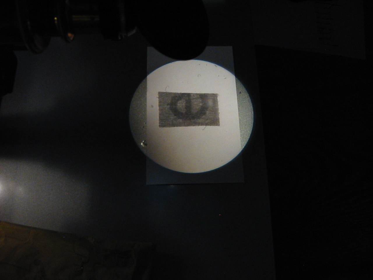
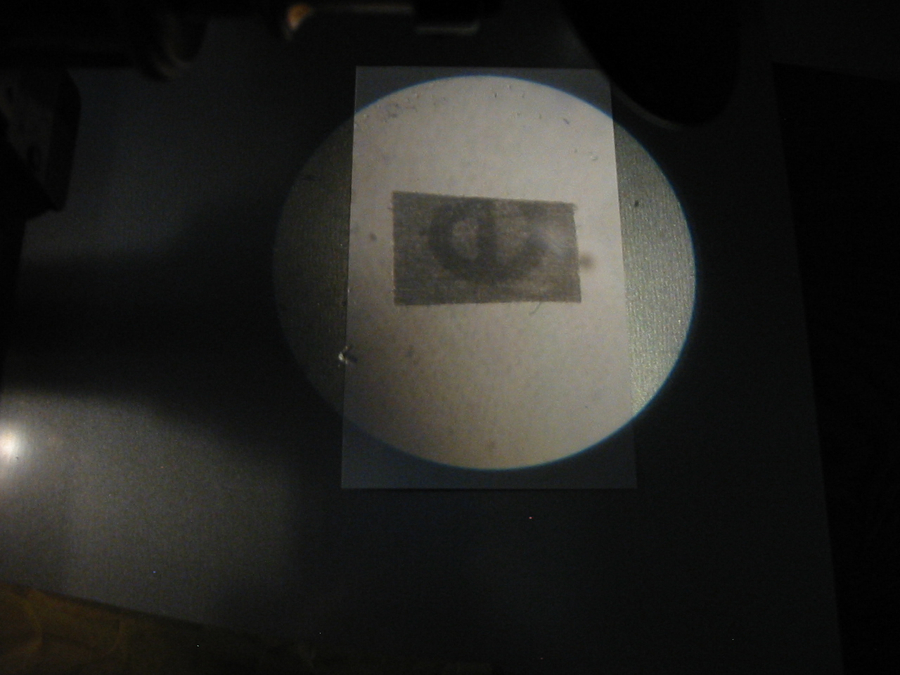
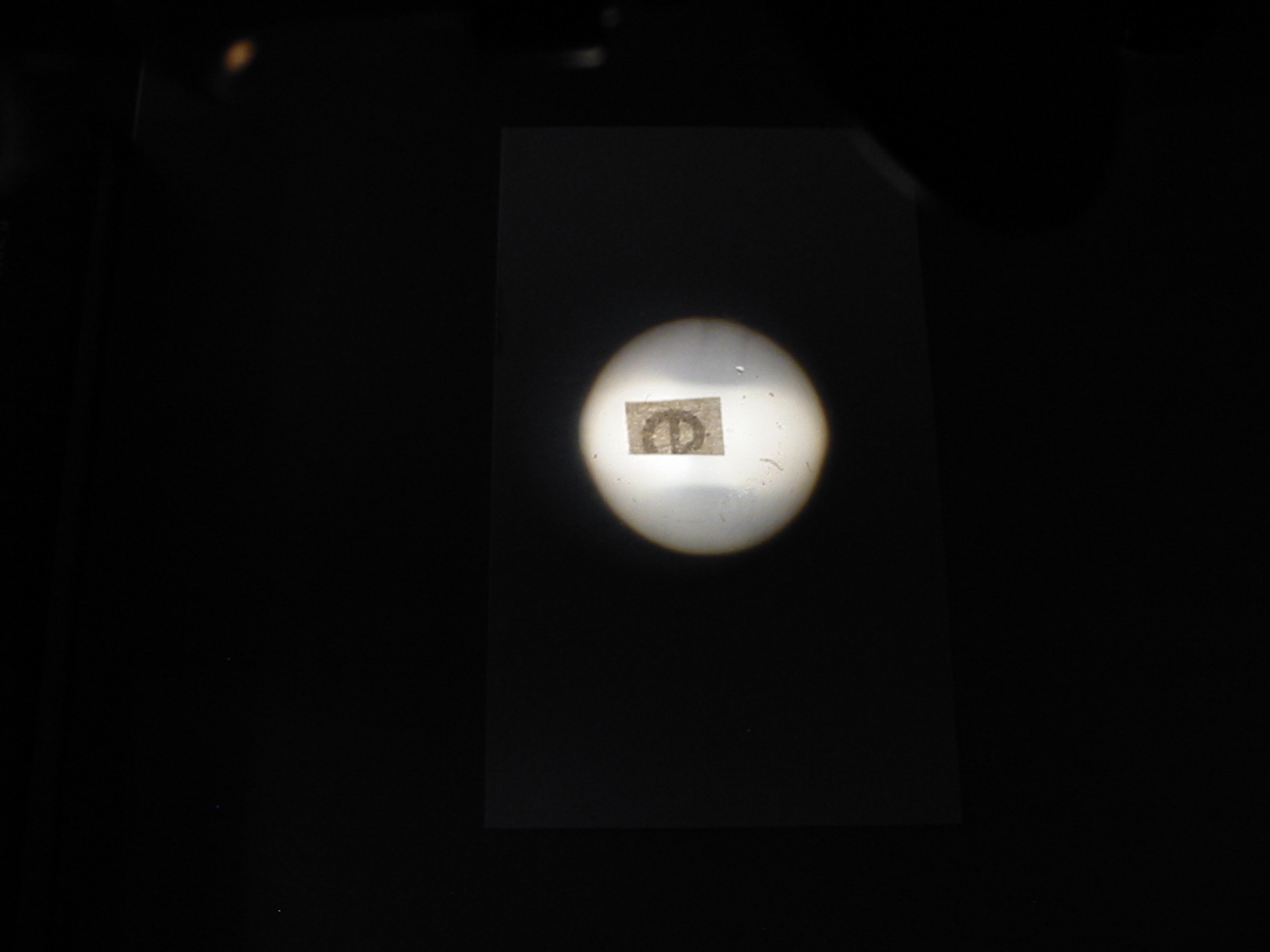
One should use the same slide as well, and for that slide no better may be selected than a permanent or temporary mount of a small letter “e” upon newsprint. It will prove useful as a means of coming to a better understanding of ones microscope, is accessible to all, and comparatively easy object for sketching (although not without the opportunity for additional details). Select the smallest print to be found and mount the letter erect upon the slide.
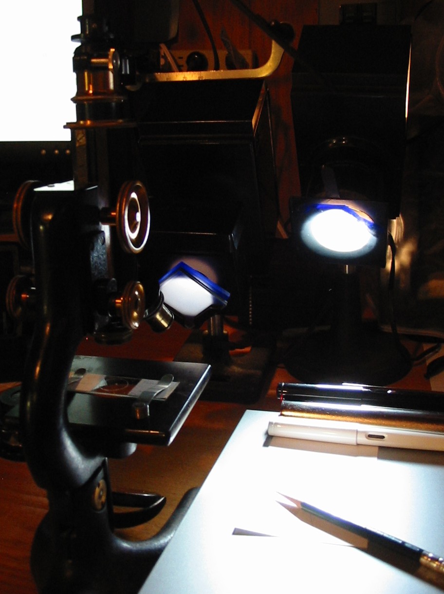
Drawing freehand from sight is an ability that is quite beyond simple instructions here though all that is needed for it is practice. Instead every effort will be made to set one down the right path to creating micrographs at the outset and skill permitted to develop naturally. However straightforward it may seem, one should not to simply look through the ocular and sketch out an image. Some fine artists may enjoy great sucess in this immediately, but mere mortals would do better to seek out every advantage. First one should consider lighting, not of the specimen but of the work area. Every effort should be made to light the room to an intensity appropriate with that seen through the ocular. For many the optical bench is often well lit which will be found excessively tiresome on the eyes when the long periods of observation required by micrography (particularly at the outset) are spent. It is helpful to use somewhat less illumination on the drawing surface than is had through the ocular.
Ninety years ago one would have made use of sunlight, an oil lantern, or even a 6volt incandescent bulb for micrography. The other options (carbon arcs for example) proving too brilliant or costly even, for high powered work that did not involve a camera. With such sources of light it was often simply a matter of drawing the shades or extinguishing the rooms other light sources; the illuminator providing light for the specimen with enough spilling out to comfortably light the drawing surface. Today those sources may still be used (often in conjunction with various improvised shades), but as ones microscope is apt to include a built in illuminator which is quite effective in limiting light leakage it becomes somewhat more of a challenge to light the drawing surface well. A desk lamp which may be equipped with a dimmer is quite useful if one is without a light source such as depicted. The drawing surface should be comfortably lit so that with one eye looking through the ocular the other may gaze upon it without straining.

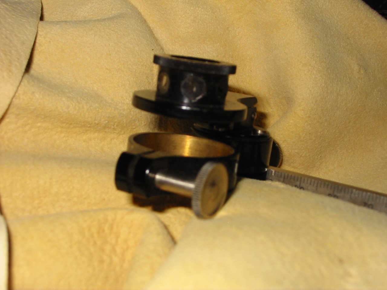
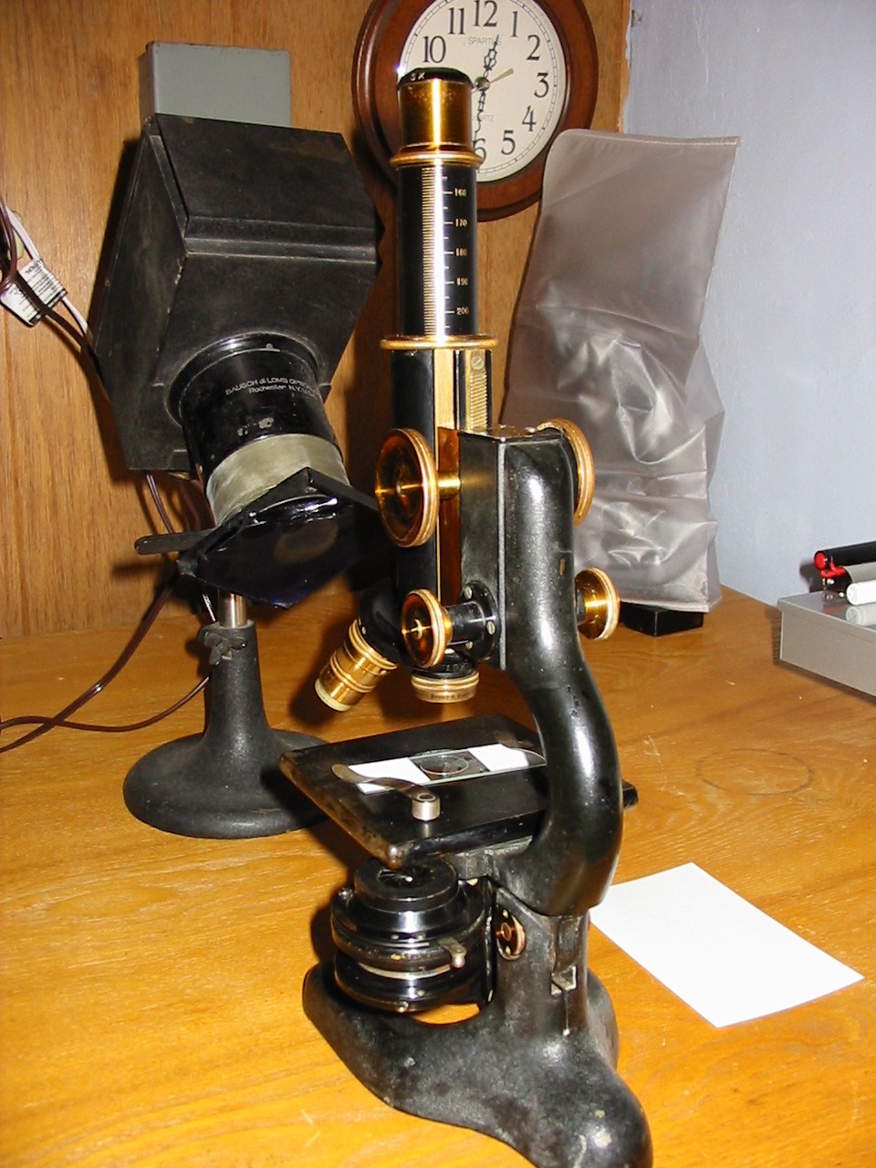
An older B&L with a lovely 32mm objective of 215mm tube length.
Which brings out the next point worth making, both eyes should be used. One eye should be always at the ocular while the other, remaining open, should gaze upon the drawing surface. This is essentially the same method one should utilize in operating a monocular microscope, except that instead of being allowed to completely relax the other eye is focused upon the drawing surface. It is something of a tiering arrangement which is why having a well lit drawing surface that is not too bright or dim is so important. If one is accustomed to wearing eyeglasses for myopia they will be need to be worn only if the drawing surface can not be seen otherwise. This is likely to prove inconvenient for those who do not possess oculars of a high eyepoint, though moving the spectacles as close to the eye as possible will often help enough that standard oculars may be used.
For paper one should use a heavy stock of very slight texture. Coarse surfaced paper will prevent one from capturing finer detail when working with sharply defined specimens and light weight papers will not bear sketching well. The plain side of a standard index card is very convenient and easily sorted and stored as well, notes being made on the reverse. Work always with a pencil initially and try not to fear making a mistake. Once the sketch is made it’s a simple matter to go in with ink if it is felt necessary.
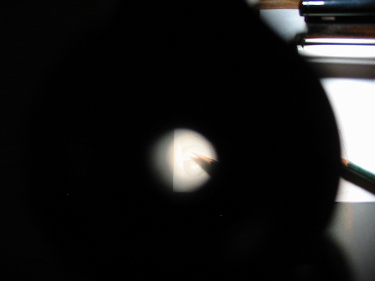
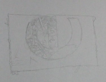
Initially one will do well to maintain the drawing surface at the same angle as the stage of the microscope, if not the same level as well. Try this experiment, focus the letter “e” slide with a low power objective and eyepiece and produce two freehand sketches. In the first sketch incline the stage of the microscope as one finds comfortable and use as the drawing surface the table on which the microscope stands. For the second sketch keep the stage of the microscope level and use something suitable to raise the drawing surface to the level of the microscope stage. Produce the sketches rapidly but not without undue care, it should not require more than a minute and only general outlines are needed.

See, no need to go for perfection!
One will find that although their is no special optical apparatus in use (save the microscope of course) the brain processes the image differently when the drawing surface is not at the same inclination as the microscope stage and the sketch in the first instance is rather elongated on the axis of inclination. Additionally, note that although the degree of magnification employed was consistent in each sketch (a 5x ocular and 32mm objective) the first ended up somewhat larger than the second. By making use of each eye simultaneously the manner in which the brain processes the image is such that the first sketch is produced larger to account for the added distance. If one wishes to get into the matter a series of experiments may be made with optics of similar magnification and different equivalent focus (remember most microscope optics produce a magnified virtual image that is seen as though 25cm from the eye) which will prove diverting… but back to micrography.
On the back (generally ruled side) of the cards mark notes regarding the image and the setup by which it was produced. At a minimum include the objective and ocular used and relative position of the microscope and drawing surface. The date and information about the slide would be well included but are not essential, the thing here is to get into the habit of producing micrographs in something of a consistent manner.
One should produce a quantity of quick sketches making use of differing arrangements of microscope and drawing surface until a useful preference is discovered. Some will find that they prefer to have only the table while others may favor some elevated and angled drawing surface. The idea is to get into the habit of using each eye simultaneously and abolish that fear some people have in setting lead to paper. These micrographs are not liable to stand publication but there is no reason to feel anything other than pride in them however they come out, it’s a dying art and any effort in keeping it alive should be commended.
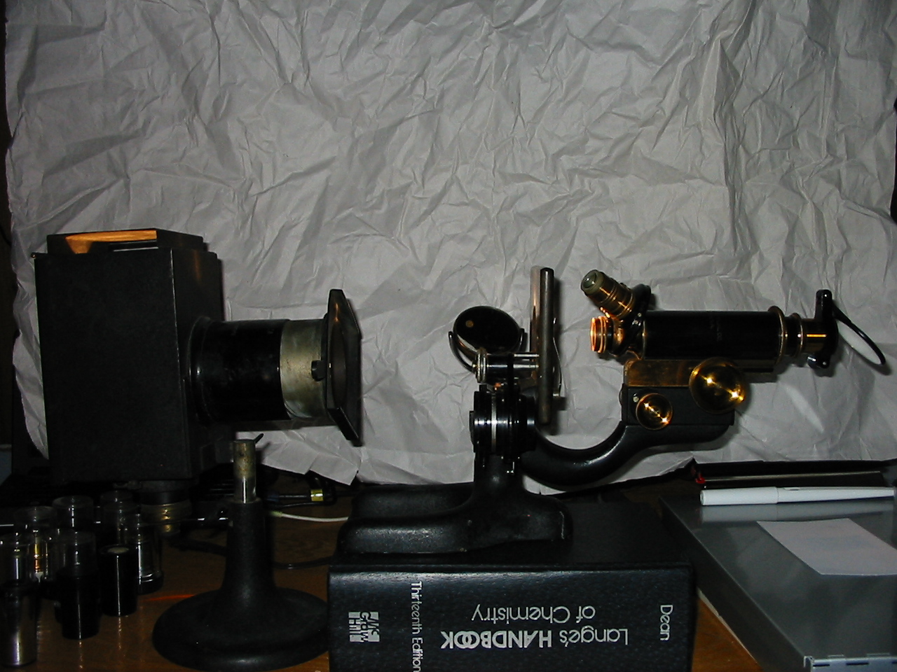
Aside from that consider my quick sketches from above, and the slide from which they were made. On the slide the letter “e” was mounted erect and seen on the stage before me appeared as it would when reading. In the sketch the letter was reversed along both the horizontal and vertical axis. Now in my case I was using a rather simple compound microscope having only the obvious optical components. There are no prisms or lenses hidden away in the body tube and no inclined head to consider. If I were to use an AO Spencer One-Sixty or a B&L Balplan with their accompanying internal optics how might I expect my sketch to differ and what would that mean is going on inside the body of the microscope? It’s all well and good to note the way in which the image moves when the slide is manipulated but a clearer understanding is certain to be had by considering the optics at play in microscopes of differing construction.
Monocular microscopes are of course well suited to this application but there is no reason one should not be able to employ a binocular head if that is all which is available. Simply use only one (that which is on the side of ones dominant hand) of the two ocular tubes and proceed as if a monocular set up were employed. A right handed individual would place their left eye at the right most ocular and view the drawing surface with the right eye.
Next time: Graticules and Huygenian Oculars!