Don’t follow my advice on developing, I know microscopes; not photography. -K
Of all the books on photomicrography perhaps the most in depth is that written by Dr. Roy M. Allen. As technical as it is the book is not without its own charm. Buried in a footnote, Dr. Allen relates his first attempt at photomicrography as a child in the late 19th century. He made his images with a box camera, using the sun for illumination.
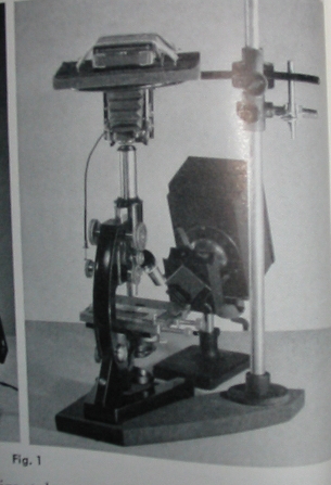
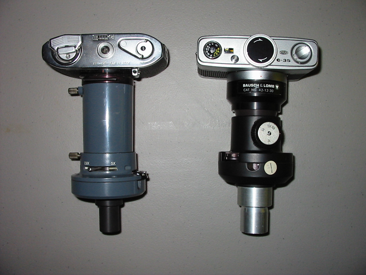
Having a box camera on hand, I thought I might give the process a try. The camera is an Agfa Ansco Shur-Shot B2 manufactured a few towns over from me in Binghamton, New York back in the 1930’s. It’s a wonderful camera for this, shooting widely available 120 film and featuring a shutter that provides for both short (approximately 1/50th) and long (B style) exposures. Unfortunately, the cameras lens is a hyperfocal meniscus lens that is less than optimum for photomicrography. A quick examination showed that the lens was held in by a simple tension ring and could be easily removed without causing any damage.
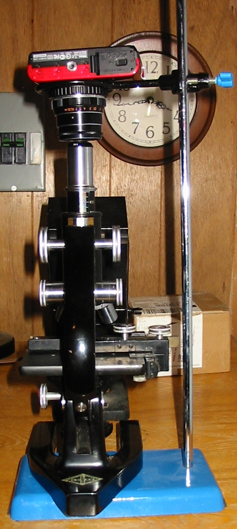
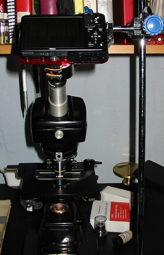
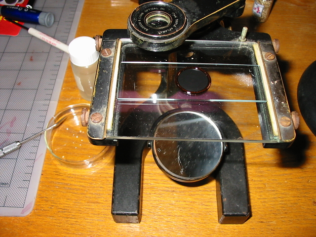
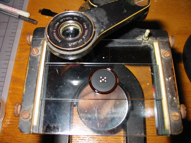
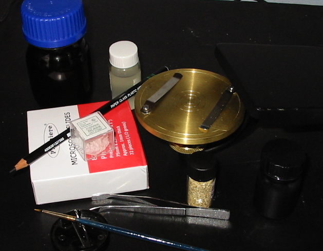
Using a lab jack made elevating the camera to the microscopes eyepiece very simple, though a stack of books could do just as well. A bright illuminator (a halogen lamp by B&L) that dates to the same period as the microscope and the camera, rounds out the setup. By using such a bright illuminator I hoped to keep the exposures short and avoid the vibration of operating a manual shutter.

The low power magnification didn’t require a condenser so a stand with a simple disc substage was used.
The depth of the box is less than 147mm, so photo and projection eyepieces are out, and a standard 5x Huygenian eyepiece was used. Thankfully, spherical aberration was less than I might have expected using achromatic objectives and a bellows length of less than 125mm. As box cameras have ground-glass view finders that are independent of the lens, (the two circular lenses seen on the right of the camera above) focusing can not be done through the camera once film is loaded. Prior to loading one may hold a paper or ground glass at the rear of the camera to determine the size of the image formed. A simple paper tube covered at one end and having a length equal to the distance from the cameras shutter to the film, serves as a focusing screen. Exposures are made by focusing with the tube and then replacing it with the camera and depressing the shutter.
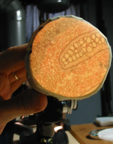
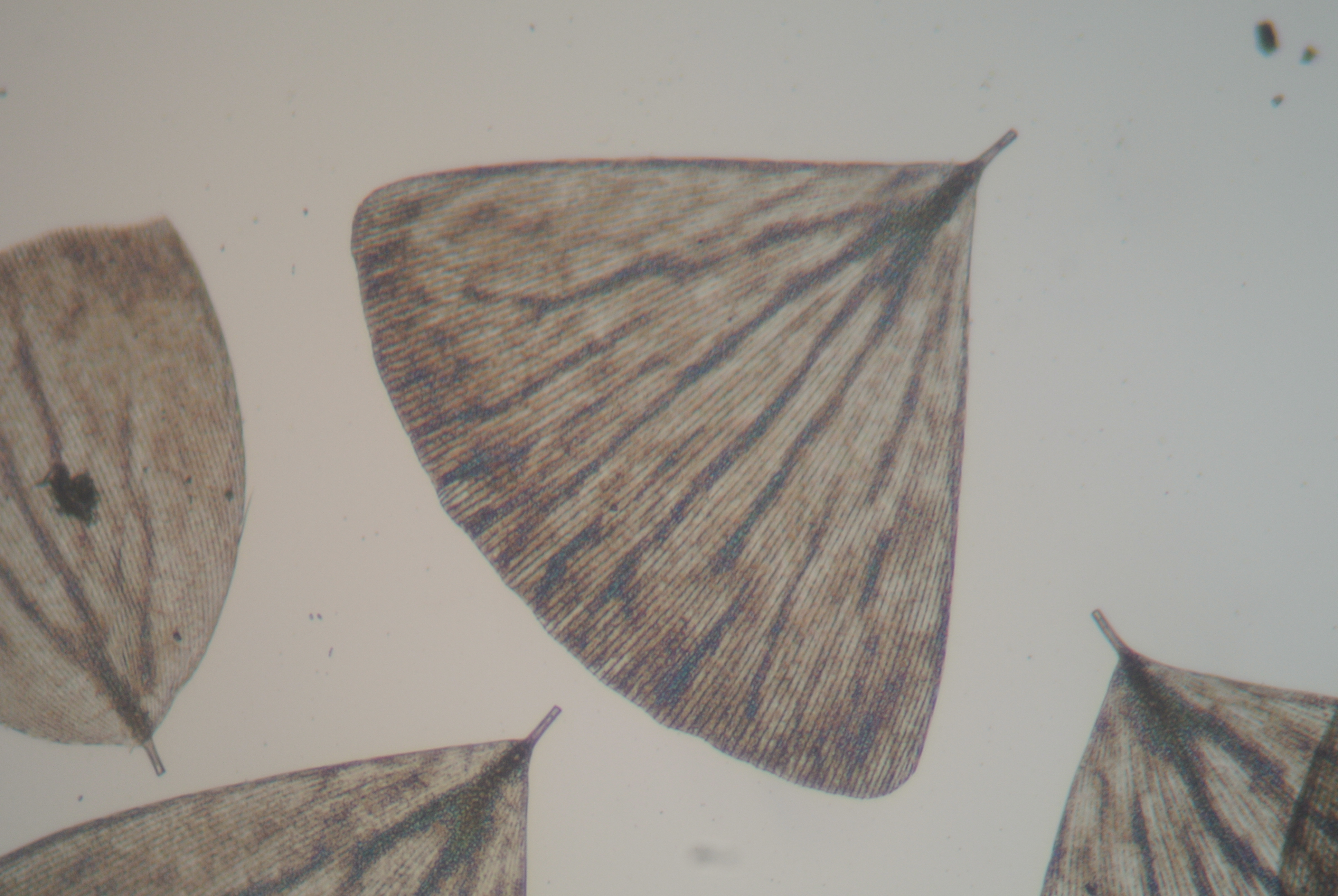
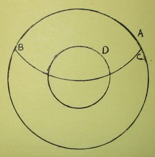
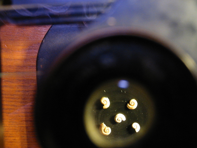
An image as seen though the focusing tube.
With the film loaded into the camera and the intended slides at hand it is only a few minutes before I have a roll of B&W 120 film ready for developing.
After loading the film onto a reel and placing it into a developing tank in a changing bag, I processed it for 15 minutes with Pyro-Metol Kodalk followed by a plain water stop bath. Next the developer was poured into a beaker and the fixer went into the tank for six minutes. I used an alkali rapid fixer known as TF-4. Following the fixer, the film (now safe to expose to light) went into the used developer for two minutes prior to a 30 minutes wash.
Presto! A roll of 8 photomicrographic negatives having the classic circular aspect and clarity of medium format. Each negative image measures 45mm in diameter. All in all, the results seem rather nice considering the film I used was some Kodak T-Max 100 that expired back in the mid 1980’s and came to me via eBay for just a few dollars.
The question now is whether to get a negative scanner or a darkroom for making prints.
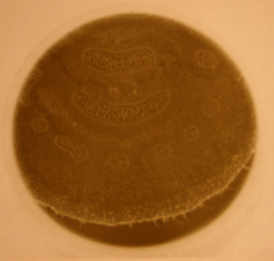
The digital photo does not do the clarity of this negative justice.